Installation instructions (cont’d) – Reznor UDBS Sizes 30, 45, 60, and 75 Option - Installation - Aesthetic Concentric Adapter User Manual
Page 4
Form I-UDAS/UDBS-ASC, PN209344R6, Page 4
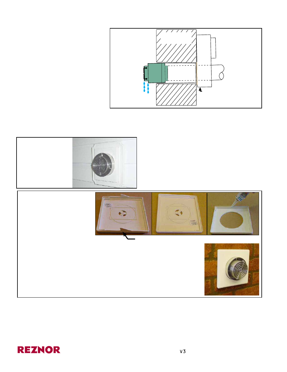
Push concentric adapter box
upward so that concentric
pipes are on a slight down-
ward slope to the outside.
Concentric pipes
(3 vent pipe
inside 4 com-
bustion air pipe)
Combustible or
Non-combustible
Wall
Rain water should
drain out and not
roll into the pipes.
FIGURE 5 -
Secure the
concentric
adapter box
with a slight
slope as
illustrated.
www.ReznorHVAC.com; (800) 695-1901
©2014 Reznor LLC, All rights reserved.
Trademark Note: Reznor
®
, T
CORE
2®
, and
®
are registered in at least the United States.
05/14 (Serial No. Date Code BNE) Form I-UDAS/UDBS-ASC (Version A.1)
FIGURE 6B - Example
of a Vent Terminal on a
Brick Wall using a field-
supplied vinyl surface
block adapted for the
purpose
Installation Instructions (cont’d)
FIGURE 6A -
Example of a Vent
Terminal on a Vinyl
Sided Installation
using a field-
supplied vinyl
mounting block
•
Left view above shows the rear side of a standard vinyl surface block.
• Center view above shows the surface block with the tabs removed.
• Right view above shows the surface block with a 4-1/8” (105mm) diameter
hole in the center. Just prior to placing the surface block on the wall, put a
generous bead of silicone sealant along the top edge. The sealant will serve
as waterproofing and to secure the surface block to the wall.
• Bottom right shows the vent terminal with vinyl block finish installed in a brick
wall.
Cut tabs off so block will fit flat.
4. Install the assembled box and vent/
combustion air terminal.
Slide the terminal end out through
the hole in the wall; 4” pipe should
extend 1-1/2” (38mm). Using the
brackets furnished with this option or
field fabricated brackets, position the
concentric adapter box against the wall.
When securing the concentric adapter
box, be certain to upward bias the box
to cause a slight downward slope of the
concentric pipes to allow any rain water
that may enter the pipes to drain to the
outside. (See
FIGURE 5.) Attach box
securely.
5. Complete the installation of the venting system following the requirements shown in
FIGURE 1 and the venting instructions in Form I-UD-V-SC (furnished with the heater).
6. Seal the outside vent terminal. Use either field-supplied grout or mortar to seal
the gap between the vent terminal and surrounding material or use finishing blocks
(available at local builders’ supply center) as illustrated in
FIGURES 6A and 6B.
On an installation with vinyl siding, the vent terminal may
be finished by adding a vinyl mounting block as shown in
FIGURE 6A.
For an installation with the outer wall made of brick or
masonry, a vinyl surface block may be adapted as shown
in
FIGURE 6B.
7. Installation of the Option CC14 kit is complete. Before operating the heater, verify
compliance with all venting requirements.
Follow the instructions in the heater manual to complete the installation.
®