Installation instructions (cont’d), Table 1 - pipe diameters and vent length, Table 2 - horizontal vent terminal clearances – Reznor UDBS Sizes 30, 45, 60, and 75 Option - Installation - Aesthetic Concentric Adapter User Manual
Page 2
Form I-UDAS/UDBS-ASC, PN209344R6, Page 2
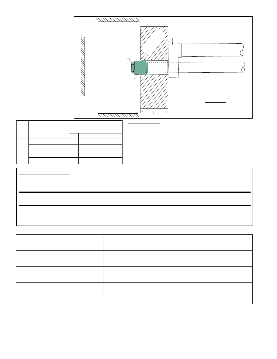
FIGURE 1 - Side
View of Horizontal
Vent using Option
CC14 Concentric
Vent/Combustion
Air Terminal
Building Overhang
Building Projection
Adjoining Building
Option CC14
Vent/Combustion
Air Terminal
4 Combustion Air
Pipe to the Heater
**3 or 4 Vent Pipe from the Heater -
See TABLE 1 for maximum length.
Painted Concentric Adapter
Box extends only 3 (76mm)
from the wall.
1(25mm) minimum; 48(1219mm) maximum
9 (229mm)
minimum
36 (914mm)
minimum
9 (229mm)
minimum
1-1/2 (38mm)
*3 vent pipe inside 4 combustion air pipe.
**4 vent pipe requires a tapered adapter to
join the vent pipe run from the heater to the
3 vent pipe extending through the concentric
adapter box. Adapter should be within 6
(152mm) of the box. 3 vent pipe run requires
a tapered adapter to connect the vent pipe
to the 4 collar on the heater.
Concentric
Pipes*
Combustible or
Non-combustible
W
all
Installation
Instructions
(cont’d)
TABLE 1 - Pipe
Diameters and Vent
Length
(All pipes
and adapters are field
supplied; see NOTES.)
TABLE 1 NOTES:
A
Category III vent pipe is required.
B
Single-wall pipe with all joints sealed or Category III pipe.
C
Requires a tapered adapter at the 4” heater outlet.
D
Requires a tapered adapter to connect the 4” vent pipe from
the heater to the 3” inner concentric vent pipe attached to the
terminal. Required length of the 3” vent pipe is the sum of the
width of the wall plus 5” (127mm).
TABLE 2 - Horizontal Vent Terminal Clearances
UDAS & UDBS
Pipe Diameter (inches) Maximum
Length
Equivalent Length
of 90° Elbow
Vent
Pipe
A
Combustion
Air Pipe
B
Ft
M
Ft
M
30 &
45
3
C
4
10
3
2
0.6
4
D
4
10
3
2
0.6
60 &
75
3
C
4
10
3
3
0.9
4
D
4
15 4.6
3
0.9
Structure
Minimum Clearances for Vent Terminal Location (all directions unless specified)
Forced air inlet within 10 ft (3.1M)*
3 ft (0.9M) above
Combustion air inlet of another appliance
6 ft (1.8M)
Door, window, or gravity air inlet (any building
opening)
4 ft (1.2M) horizontally
4 ft (1.2M) below
1 ft (305mm) above
Electric meter, gas meter ** and relief equipment
U.S. - 4 ft (1.2M) horizontally; Canada - 6 ft (1.8M)
Gas regulator **
U.S. - 3 ft (0.9M); Canada - 6 ft (1.8M) horizontally)
Adjoining building or parapet
***3 ft (.9M)
Adjacent public walkways
7 ft (2.1M) above
Grade (ground level)
3 ft (.9M) above****
*Does not apply to the inlet of a direct vent appliance. **Do not terminate the vent directly above a gas meter or service regulator. *** Clearance
based on certification testing. **** Consider local snow depth conditions. The vent must be at least 6” (152mm) higher than anticipated snow depth.
3. Assemble the field-supplied concentric pipes, the vent terminal, and the
concentric adapter box.
a) Cut to length the field-supplied, 3-inch diameter vent pipe that will be the inner
portion of the concentric pipes:
Length must be at least 5” (127mm) plus the thickness of the wall. The inner (vent)
pipe must be one piece of continuous pipe.
Vent Pipe Condensation: On units with long vent runs (over 50% of maximum vent length allowed) or installed
in low ambient conditions (below 50°F), it is recommended that the vent pipe be fitted with a tee, a drip
leg, and a cleanout cap to prevent moisture in the vent pipe from entering the unit. The drip leg should be
inspected and cleaned out periodically during the heating season.
CAUTION: Exceeding the specified vent pipe diameter and length may result in condensate
forming in the vent pipe.
The horizontal vent run
must be pitched down toward the terminal end 1/4” per foot for condensate drainage. The
slope applies to the entire length of the horizontal vent run. Failure to pitch the vent run properly may damage the
heater due to condensate running back into the unit.