Installation instructions (cont’d) – Reznor UDBS Option - Installation - Downturn Nozzles - V3 User Manual
Page 4
Form RZ-NA I-V3-DN, P/N 197101 Rev 5, page 4
2. Install the Vertical Louver Frame
Position the assembled louver frame in the nozzle outlet so that the holes in the
tabs on each side are lined up with the holes in the nozzle. (The tabs fit between
the horizontal louvers.)
Using the screws in the kit, attach the tabs to the sides of the nozzle outlet.
3. Install the Vertical Louvers in the Louver Frame Using the Compression
Springs (See FIGURE 4.)
Before actually installing the louvers, note the louver curve and determine how
the louvers should be positioned to provide the optimal throw pattern. Depend-
ing on where the heater is installed and the desired direction of airflow, louvers
may be installed with the curve all the same direction (either way) or the right
half one way and the left the other as illustrated in
FIGURE 4.
a)
With the wider section facing out of the heater, place one of the com-
pression springs over the tab on the notched end of the louver.
b) Depending on the throw pattern selected, the end with the spring can go
either in the top support or the bottom. See
FIGURE 4. Slide the tab with
the spring into one of the holes in either the top or bottom support. Push the
louver, compressing the spring enough to place the tab on the other end
into the corresponding hole in the other support.
c) Continue installing the louvers until all vertical louvers are in place.
APPLICATION NOTE:
Option CD5 may only be
installed on Model UDBP or
UDBS;
DO NOT install CD5
on a Model UDAP, UDAS, or
UEAS.
Installation
Instructions (cont’d)
www.ReznorHVAC.com; (800) 695-1901
©2014 Reznor LLC, All rights reserved.
Trademark Note: Reznor
®
, T
CORE
2
®
, and
are registered in at least the United States.
05/14 (Serial No. Date Code BNE) Form I-V3-DN (Version A.3)
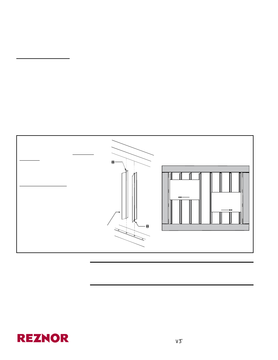
FIGURE 4 - Installing
Vertical Louvers in
Option CD4 or CD5
4. Adjust the horizontal and vertical louvers to provide the desired throw pattern.
CAUTION: To avoid getting burned, adjust louvers while heater
is not in operation. If louvers are adjusted while heater is in
operation, wear protective gloves.
Installation of Option CD4 or CD5 is complete. If the heater is installed, turn on
the electric and the gas. Light by following the lighting instructions on the heater.
Check for proper operation.
1) On the notched end of the
louver, slide the spring over the tab.
2) When facing the unit, for airflow
to the left, push the tab with the spring
into a hole in the top louver frame
(compressing the spring) and insert
the tab on the other end into the
corresponding hole in the bottom.
For airflow to the right, push the tab
with the spring into a hole in the
bottom louver frame (compressing
the spring) and insert the tab on the
other end into the corresponding hole
in the top.
Wider side of the louver
blade must always be
facing out of the heater.
Airflow directed
to the left;
springs are
on the top.
Airflow directed
to the right;
springs are on
the bottom.
Front View of Vertical Louver
Frame with Louvers Installed
(Nozzle is removed for clarity.)
SECTION B - Options
CD4 and CD5 (cont’d)
®