Applies to, Option cd4, Option cd5 – Reznor UDBS Option - Installation - Downturn Nozzles - V3 User Manual
Page 3
Form RZ-NA I-V3-DN, P/N 197101 Rev 5, page 3
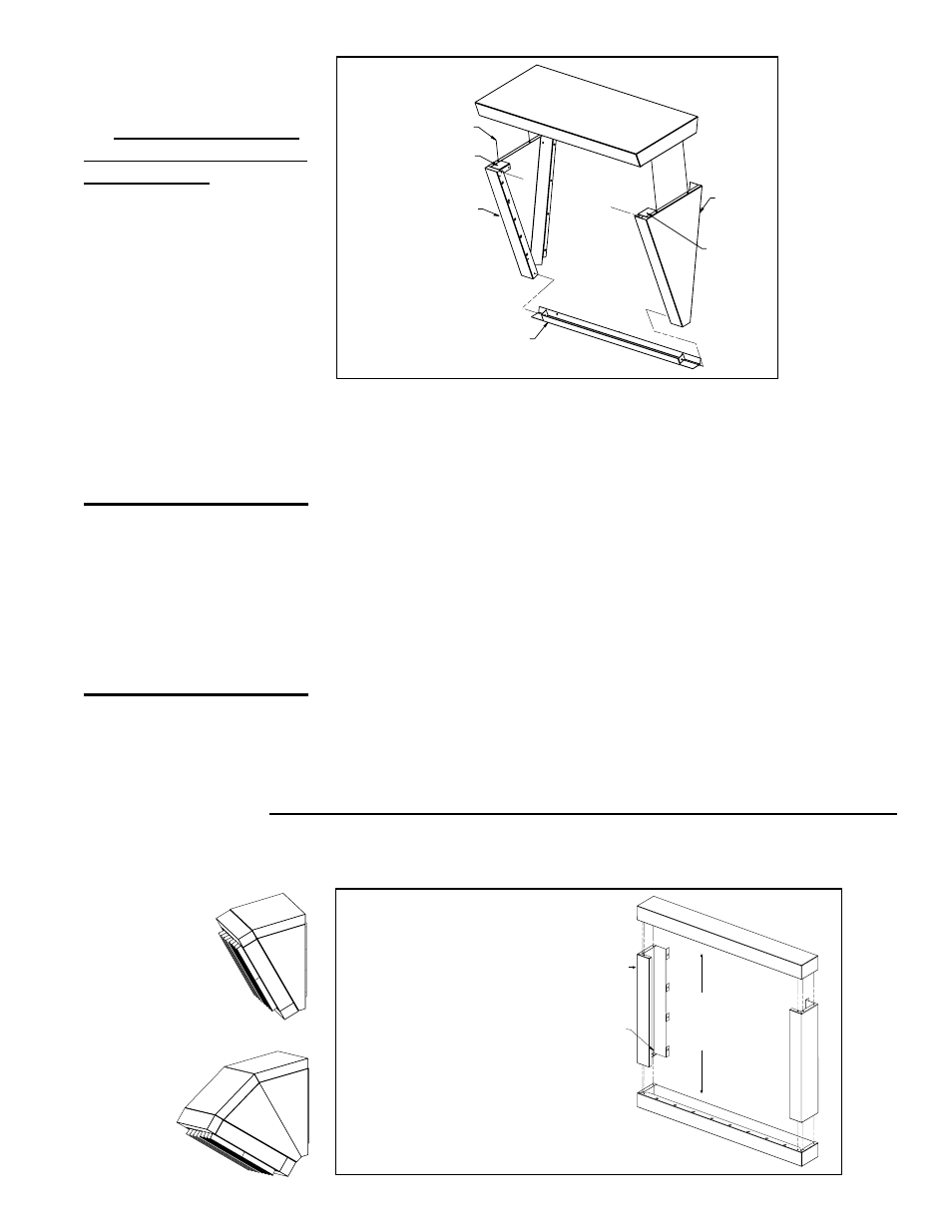
Nozzle
Left Side
Nozzle
Bottom
Nozzle
Right
Side
Nozzle Top
Attach top and sides
using the bracket
and screws from
the option package.
Nozzle
Bracket
Nozzle
Bracket
FIGURE 2 -
Assembling the
downturn nozzle
for UDAP, UDAS, UDBP,
UDBS Sizes 150-400 and
UEAS 130-310.
Install a nozzle bracket
in the top front corners
of each section.
3. Remove the Horizontal Louvers from the Heater
The louvers in the heater outlet are spring mounted. Push on each louver
blade compressing the spring so that the louver is released from the opposite
end and can be pulled out of the heater outlet. Remove all louver blades being
careful not to lose the springs. Save louvers to be re-installed in the nozzle
opening.
4. Install the Assembled Downturn Nozzle in the Heater Outlet
Position the assembled nozzle in the heater outlet so that the holes on each side
are lined up with the holes in the heater.
Using the screws in the kit, attach the nozzle to the sides of the heater outlet.
If installing Option CD3 or CD5, position the second assembled nozzle in the
outlet of the nozzle already attached to the heater. Attach the second nozzle to
the first nozzle creating a downturn with two sections.
5. Install the Louvers in the Nozzle Outlet
Install the spring loaded louvers removed in Step 3. in the nozzle outlet. Adjust
the louvers to provide the desired air throw.
CAUTION: To avoid
getting burned, adjust
louvers while heater
is not in operation. If
louvers are adjusted
while heater is in
operation, wear
protective gloves.
Option CD2 or CD3 - Installation is complete. If the heater is installed, turn on the
electric and the gas. Light the heater following the lighting instructions. Check for
proper operation.
Options CD4 and CD5 - Continue to SECTION B.
SECTION B
Assemble
louver frame
with screws.
Louver Frame
Side (side parts
are identical)
Louver Frame
Top or Bottom
(parts are
identical)
1. Assemble the Vertical Louver Frame (See FIGURE 3.)
Using the screws in the kit, attach both sides to the top. (NOTE: Top and bottom
are identical.) Attach the assembly to the bottom creating a frame.
FIGURE 3 -
Assemble
the Vertical
Louver Frame
Applies to
Option
CD4
Option
CD5