Fan, fan guard or motor replacement, Contactor, Transformer – Reznor EXUB Unit Installation Manual User Manual
Page 8: Printed circuit board, Thermal delay fuse, Warning, Repair and replacement, continued
8
Fan, Fan Guard or Motor Replacement
The motor is a sealed unit that requires no lubrication. If the motor is defective, it must be replaced with
an original factory supplied motor.
1. Remove four bolts holding motor to the motor mount, and covers from junction box and control enclosure.
On units with an integral room thermostat, remove 4 bolts on front face of thermostat enclosure .
2. Detach and remove two-piece fan guard assembly by removing top and bottom screws that attach the fan
guard to the cabinet.
3. Loosen fan blade set screw and remove fan blade from end of motor shaft leaving it in fan panel opening.
4. Unscrew the expansion union fitting between motor and motor enclosure (or integral thermostat enclosure).
5. If replacing motor, note wire connections for future reference and cut all wires leading to the motor close
to the terminations. All motor wires are permanently marked according to the nameplate on the motor. Lift
the motor assembly off the motor mount.
6. If replacing fan blade only do not cut any wires and move the motor assembly back sufficient to assist fan
blade removal.
7. To reassemble, place fan blade inside fan panel opening and then place motor onto motor mount. Slip fan
blade onto motor shaft and ensure fan hub is flush with end of motor shaft. Tighten set screw to 150 in-lbs
torque.
8. Fasten the two-piece fan guards to the cabinet.
9. Tighten conduit fittings between motor and motor enclosure
(or integral thermostat enclosure). Center fan in fan-panel
opening and leave approximately 1/16” to 3/16” (1.6 to 4.8
mm) gap between motor face and fan guard.
10. Bolt motor to motor mount, tighten nuts to 250 in-lbs torque.
Manually spin the fan blade to ensure it rotates freely before
reconnecting heater to power supply. Fan must rotate
counterclockwise when viewed from rear of heater.
Contactor
1.
Loosen, but do not remove contactor mounting screws. Slide contactor off mounting screws.
2.
Replace with a factory supplied contactor of the same rating.
Transformer
1.
Replace with a factory supplied transformer of the same rating.
2.
On the new transformer, select primary wires to match heater voltage. Ensure that the correct transform-
er secondary lead is grounded (see wiring diagram). Individually terminate all unused wires using closed
end connections.
Printed Circuit Board
1.
Replace with a factory supplied P.C. Board.
Thermal Delay Fuse
1.
Replace fuse with one of the same type and rating as indicated on P.C. Board or refer to parts list. An
extra fuse should be stored in the clips marked “SPARE”.
— WARNING! —
Heater is to be serviced only by qualified electrician experienced with hazardous location equipment.
Explosion/Electric Shock Hazard. Disconnect heater from power supply or fuse box before opening
enclosures or servicing heater. Lock the switch in the “OFF” (open) position and/or tag the switch to prevent
unexpected power application.
— Repair and Replacement, Continued —
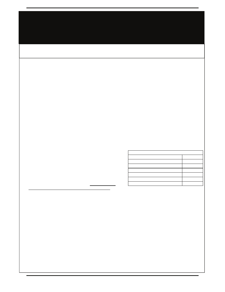
Torque Settings
Item Torque
(in-lbs)
Fan blade set screw (1 only)
150
5/16 - 18 UNC motor nuts
250
5/16 - 18 UNC motor mount bolts
250
1/4 - 20 UNC fan panel bolts
100
1/4 - 20 UNC fan guard self tapping screws
100
#10 - 24 UNC louver blade screws
28