Installation — electrical, Warning – Reznor EXUB Unit Installation Manual User Manual
Page 6
6
— INSTALLATION —
Electrical
1. Heater is to be connected and serviced only by qualified electrician experienced with hazardous location equipment. It is the responsi-
bility of the installer to verify the safety and suitability of the installation.
2. Explosion/Electric Shock Hazard. Disconnect heater from power supply or fuse box before opening enclosures or servicing heater.
Lock the switch in the “OFF” (open) position and/or tag the switch to prevent unexpected power application.
3. Use copper conductors only for supply wires and approved explosion-proof means of wiring during installation. Use minimum 90°C
rated wire. Refer to “Supply Wire Requirements” table and heater data plate for conductor wire rating.
4. Installation must include appropriate over-current protection devic-
es (fusing or circuit breakers) as required by the CEC or NEC.
Refer to “Supply Wire Requirements” table and heater data plate
for current ratings. Supply voltage is to be within 10% of the data
plate voltage.
5. Confirm that the electrical power supply matches the nameplate
voltage, phase, amperage and frequency rating of the heater to be
connected.
6. Supply conductors and ground conductor pass through the 1 in.
NPT rigid conduit opening on the control enclosure.
7. Proper installation of the heater requires that an adequate ground-
ing conductor be connected to the ground terminal. This terminal is
made of copper and is located on the top right-hand corner of the
printed circuit board within the control enclosure.
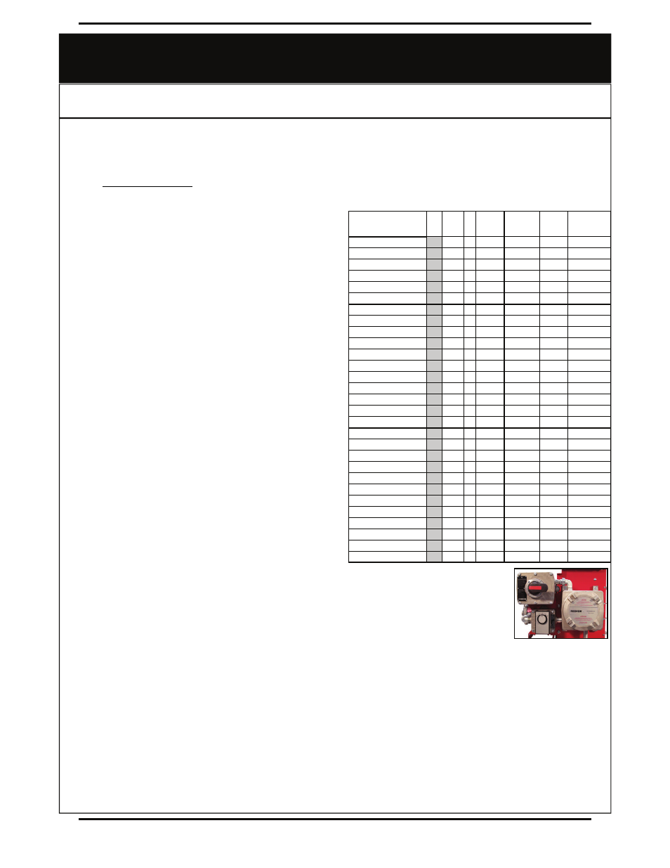
8. Heater may be supplied with a factory installed integral room ther-
mostat (See Figure 1). On heaters not supplied with this option, it
is recommended that an external explosion-proof room thermo-
stat be used. The wiring to the external thermostat must be copper
wire, 16 gauge minimum (for Class II) or 14 gauge minimum (for
Class I). Thermostat conductors may also be passed through the 1
in. NPT conduit opening or through the convenient 3/4 in. NPT
dedicated external thermostat conduit opening in the enclosure.
Connect the external thermostat conductors to the printed circuit
board terminal block marked “T’STAT”. The built-in control trans-
former supplies the heater with either 120V or 24V for internal unit
operation. This voltage will appear across the thermostat contacts
when they are open. The minimum thermostat contact rating
should be 1 amp @ 120 VAC. Refer to nameplate for control volt-
age of unit.
9. Refer to wiring diagram on Page 9 to ensure that all connections
are as required and securely fastened.
10. For heaters supplied with a factory installed integral disconnect
switch (See Figure 1), field wiring is as follows:
a. Remove the Disconnect cover assembly from the base by removing the six (6) cover bolts. Set the cover
assembly aside. CAUTION: Damaging the mating surfaces of the enclosure could destroy the flame path
and jeopardize the integrity of the flame proof enclosure.
b. Supply conductors and ground conductor pass through the 1 in. NPT rigid conduit opening located on the
top or bottom of Disconnect Enclosure. Supply conductors to be wired to DIN rail mounted Disconnect
Switch inside. Ground conductor to be wired to Ground Lug fastened to inside of Disconnect Enclosure.
Refer to wiring diagram on Page 9.
c. Attach cover to the enclosure using the six (6) bolts. Tighten to 150 inch-pounds ± 5 in-lbs.
11. All unused threaded openings in enclosures, not used for supply wiring or external room thermostat, must be fitted with threaded plugs
approved for use in hazardous locations (included). Factory installed conduits require no additional sealing.
12. Installer must seal each conduit run within 18” (457 mm) of enclosure. This seal must be suitable and listed for hazardous locations.
13. Ensure that input conductors and conduit have adequate strain relief at installation.
14. Before application of electrical power, recheck all connections to ensure compliance with the wiring diagram and any code require-
ments. Remove any foreign objects from the control box and heater. Reinstall cover tightly.
15. On all three-phase heaters, it is necessary to verify that the fan rotation is correct (counter clockwise when facing the rear of the
heater). If air delivery is not from the front of the heater, reverse any two supply leads at the main power contactor located in the
control enclosure.
16. The explosion-proof control enclosure and element enclosures are designed with O-rings, threaded joints and metal-to-metal contact at
the lid or cover joint to prevent an explosion. Do not attempt to install gasket material of any type at these joints. A light coating of anti-
seize compound may be applied to the threads to prevent seizing.
— WARNING! —
Read and follow the instructions in this manual. Failure to do so may result in severe or fatal injury.
Model
kW Volts Ø
Total
Current
Amps
Minimum
Circuit
Ampacity
Max F
use
Amps
Supply
Wire
90°C (AWG)
EXUB5AK2
5 208 1 26.5 33.2
35
8
EXUB5AK3E
5 240 1 23.3 29.2
30
10
EXUB5AK5
5 208 3 14.6 18.2
20
12
EXUB5AK6E
5 240 3 12.7 15.9
20
12
EXUB5AK7E
5 480 3 6.7
8.4
15
14
EXUB5AK8E
5 600 3 5.5
6.9
15
14
EXUB7AK2
7.5 208 1 38.6
48.2
50
6
EXUB7AK3E
7.5 240 1 33.8
42.2
50
8
EXUB7AK5
7.5 208 3 21.5
26.9
30
10
EXUB7AK6E
7.5 240 3 18.7
23.4
30
10
EXUB7AK7E
7.5 480 3 9.7
12.2
15
14
EXUB7AK8E
7.5 600 3 7.9
9.9
15
14
EXUB10AK3E
10 240 1 44.2
55.2
60
6
EXUB10AK5
10 208 3 28.5
35.6
40
8
EXUB10AK6E
10 240 3 24.8
30.9
35
8
EXUB10AK7E
10 480 3 12.7
15.9
20
12
EXUB10AK8E
10 600 3 10.3
12.9
15
14
EXUB15AK5
15 208 3 42.3
52.9
60
6
EXUB15AK6E
15 240 3 36.8
46.0
50
6
EXUB15AK7E
15 480 3 18.7
23.4
25
10
EXUB15AK8E
15 600 3 15.1
18.9
20
12
EXUB20AK7E
20 480 3 24.8
30.9
35
8
EXUB20AK8E
20 600 3 19.9
24.9
25
10
EXUB25AK7E
25 480 3 31.1
38.8
40
8
EXUB25AK8E
25 600 3 25.1
31.3
35
8
EXUB30AK7E
30 480 3 37.1
46.4
50
6
EXUB30AK8E
30 600 3 29.9
37.3
40
8
EXUB35AK7E
30 480 3 43.1
53.9
60
6
EXUB35AK8E
30 600 3 34.7
43.3
50
6
EXUB Supply Wire Requirements
Figure 1