Audio panel tray and connector assembly, Cable harness wiring – PS Engineering PMA7000H Installation Manual User Manual
Page 9
PS Engineering
PMA7000H Series Audio Selector Panel and Intercom System
Installation and Operator’s Manual
200-780-0429
Page 2-2
Rev. 4, Dec 2012
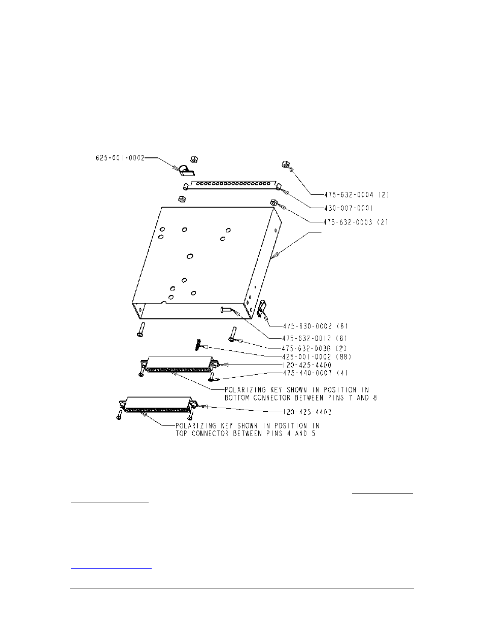
32 x ½" screws (475-632-0012). The audio selector panel must be supported at front and rear of the mount-
ing tray.
2.3.4
Audio Panel Tray and Connector Assembly
The unit connectors mate directly with the circuit boards in the PMA7000H. The connectors are a Molex
crimp-type, and require the use of a Molex hand crimp tool, EDP P/N 11-01-0203, CR6115B (or equiv.).
The connectors are mounted to the unit tray with #4-40 screws (475-440-0007), from the inside of the tray.
Ensure that proper strain relief and chafing precautions are made during wiring and installation, using the
cable clamp (625-001-0002). Secure the ground bar (430-007-0001), if desired using, #6-32 nuts (475-632-
0003) and #6-32 lock nuts (475-632-0004).
Figure 2-1 Audio Panel Tray Assembly Drawing
2.4
Cable Harness Wiring
Referring to the appropriate Appendix, assemble a wiring harness as required for the installation. All wires
must be MIL-SPEC in accordance with current regulations. Two- and three-conductor shielded wire must
be used where indicated, and be MIL-C-27500 or equivalent specification. Proper stripping, shielding and
soldering technique must be used at all times. It is imperative that correct wire be used.
Refer to FAA Advisory Circular 43.13-2A for more information. Failure to use correct techniques may re-
sult in improper operation, electrical noise or unit failure. Damage caused by improper installation will void
the PS Engineering warranty.
NOTE: PS Engineering can make a custom wiring harness for the intercom. Call 1-800-ICS-AERO or see
for details.
120-430-0420