Appendix b bottom connector interconnect, Bottom connector, j1 – PS Engineering PMA7000H Installation Manual User Manual
Page 29
PS Engineering
PMA7000H Audio Selector Panel and Intercom System
Installation and Operator’s Manual
200-780-0429
Appendix B
Rev. 4, Dec 2012
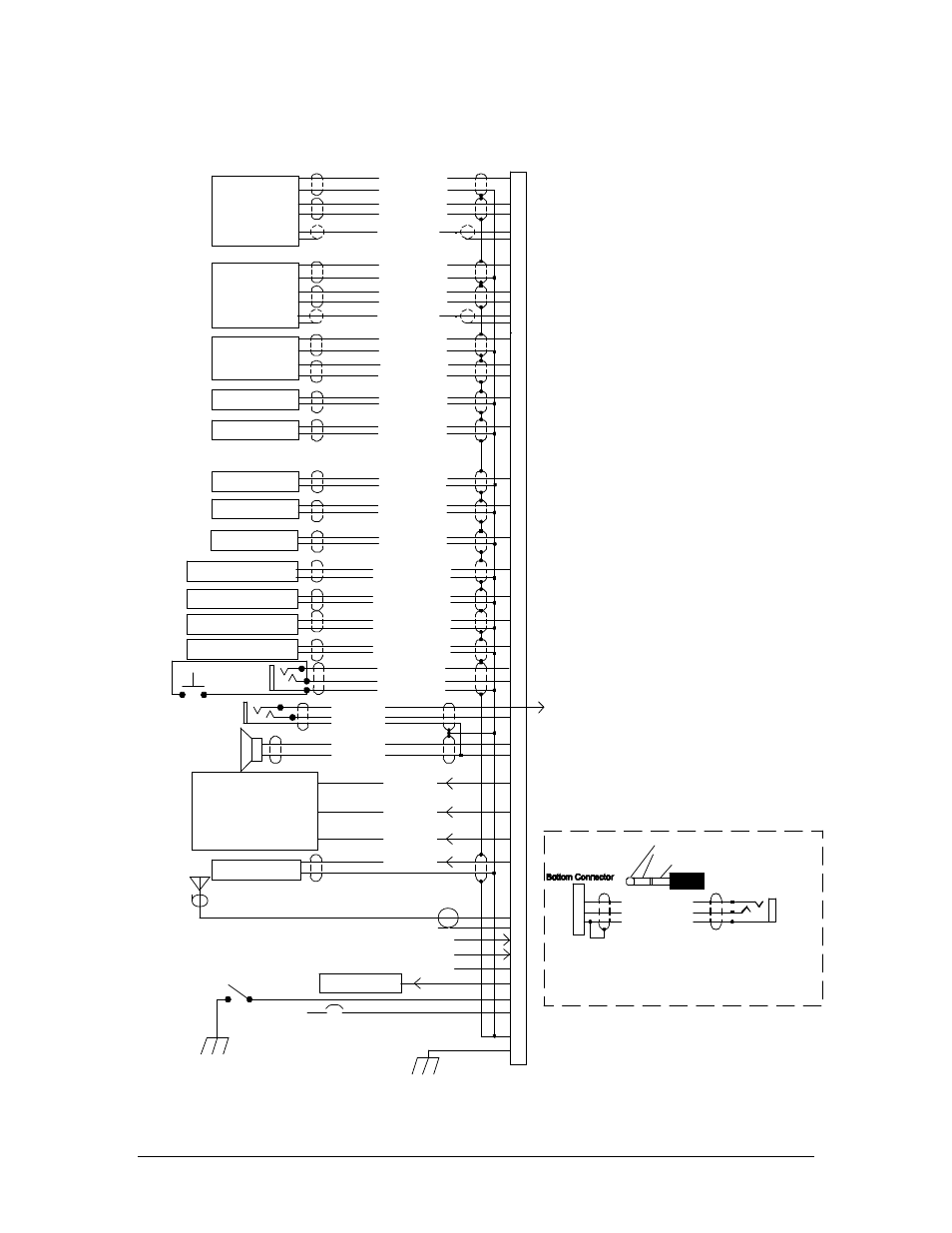
Appendix B Bottom Connector Interconnect
Com 1 Audio Hi
Com 1 Mic Key
Com 1 Lo
Communications
Transceiver #1
Communications
Transceiver #2
Nav 1 Audio Hi
NAV 1 Audio Lo
VHF Nav 1
Nav 2 Audio Hi
Nav 2 Audio Lo
VHF Nav 2
DME Audio Hi
DME Audio Lo
DME Receiver
Com 1 SPR Load
Com 2 SPR Load
Unswitched Input #1 Hi
Unswitched Audio Lo
Unswitched Audio #1
Unswitched Input #2 Hi
Unswitched Audio Lo
Unswitched Audio #2
Pilot Mic Audio Hi
Pilot Mic PTT
Pilot Mic Lo
Ext. Marker Lamp (Blue)
C
5
4
2
Ext. Marker Lamp (White)
Ext. Marker Lamp (Amber)
MM Sense Output
MKR Ant.
B
A
White Lamp Output
Blue Lamp Output
Amber Lamp
MM Sense
RG-58A/U Coax
PA Mute Trigger
F
D
E
18
14
20
1
Z
W
22
28 Volt Lights Hi
14 V Lights Hi
Lights Lo
Ground Lug
Airframe Ground
3A Breaker
11-33 VDC
9
P
R
Com 1 Mic Audio Hi
Com 2 Audio Hi
Com 2 Mic Key
Com 2 Lo
10
H
V
Com 2 Mic Audio Hi
12
13
6
19
L
Com 1 Spr Load
Com 1 Spr Load
Com 2 Spr Load
Com 2 Spr Load
16
M
T
17
Speaker Hi
Speaker Lo
3
Pilot Phones (L)
Pilot Phones (R)
Pilot Phones Lo
8
Y
To Pin 1
Top Conn.
Communications
Transceiver #3
J
K
15
Com 3 Audio Hi
Com 3 Mic Audio Hi
Com 3 Lo
Com 3 Mic Key
ADF Audio Hi
ADF Audio Lo
ADF Receiver
S
AUX Audio Hi
AUX Audio Lo
AUX Audio
11
Notes:
1. Pins 7, N, 21, are not used.
2. All shields should be grounded at audio panel only
other end remains floating.
3. Speaker and Pilot Headphone ground returns
MUST be kept separate and connected
to pin 22.
4. All Power, and Ground wires must be #18 gage wire
Lighting #22 AWG, other wires minimum #24 AWG
5. Pilot mic and headphone jacks must be isolated from ground.
6. Pin 20 connected through a 3 A breaker.
7. PA Mute is a TTL level logic output
that is pulled low when PTT active.
8. Speaker loads may be required on some
transceivers. Consult transceiver manufacturer's information.
9. Installations require a 3 A breaker.
10. Audio applied to Pins T, 17, U and X , is always presented
in speaker, pilot and copilot headphones, regardless
of SPR switch or PTT. Audio applied to Pin T is
heard in pilor right headphone in Fail-safe.
11. All shielded wires must be MIL 22750 or 27500.
12. Connect pilot headphone (L) to top connector, Pin 1,
using 3-conductor wire.
13. Key pin between pin 7 and 8.
14. Applying ground to Pin 14 places the unit in
Alternate Intercom Mode. See Section
Ext. Marker Annunciator
Pilot PTT
See Note 4, 9
See Note 7
See Note 4, 9
See Note 3
See Note 8
See Note 12
Bottom Connector, J1
Unswitched Input #3 Hi
Unswitched Audio Lo
Unswitched Audio #3
Unswitched Input #4 Hi
Unswitched Audio Lo
Unswitched Audio #4
U
X
See Note 10
3/32" Cellular Jack
COM 3 Mic Input
Com 3 Audio
Audio Lo
J
K
1
Cellular Plug (typcal)
Tip= Microphone out
Ring= Speaker audio
Base=Ground
For Duplex (cell phone) operation
Pin J of top connector MUST BE GROUNDED
This is a typical interconnect
PS Engineering does not guarantee
compatability in all cases.
Cellular Phone
Interconnect
ALT ICS Mode
Enable
See Note 14
1/8” cell jack
7000H
2.4.13.4