Com 3 duplex (tel) function for cell phones, Transmit interlock, Swap" mode – PS Engineering PMA7000H Installation Manual User Manual
Page 11
PS Engineering
PMA7000H Series Audio Selector Panel and Intercom System
Installation and Operator’s Manual
200-780-0429
Page 2-4
Rev. 4, Dec 2012
2.4.3.3 Speaker Load
The PMA7000H contains a speaker amplifier. Some units with internal speaker amplifiers, such as the
King Radio KX170, require a resistive load to prevent damage if their speaker amplifier is not used. Con-
nect the speaker output from the unit to the load input on the PMA7000H (J1, pins 19 and L, 16 and M.)
The speaker load is 16
, 3W.
2.4.4
Com 3 Duplex (TEL) Function for Cell Phones
As installed in the standard configuration, the PMA7000H Com 3 function operates conventionally. Push-
ing the Com 3 XMT button places the receive audio from Com 3 in the headset and applies the pilot or co-
pilot microphone to the Com 3 when the appropriate PTT is activated.
If J2, Pin J is connected to aircraft ground, the PMA7000H is forced into Com 3-Duplex mode. Copilot and
passenger audio as selected by hook switches are provided to the COM 3 output, the PTT for Com 3 is inac-
tive, and audio from Com 3 is presented to the headset. This allows a telephone-like audio interface. The
COM 3 input and output are compatible with aviation radios.
The COM 3 input and output are compatible with general aviation radios. However, if J2, Pin J is connected
to aircraft ground (either directly or through a switch), the PMA7000H is forced into Com 3-Duplex mode.
In this mode, the COM 3 input and output is compatible with many cellular telephones utilizing the hands-
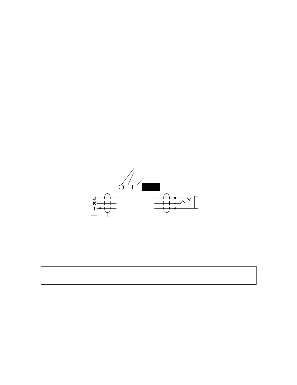
free headset interface. A 1/8" jack can be installed on the aircraft panel, which is interfaced with the
PMA7000H as shown below. To connect the cellular telephone to the jack wired in to COM 3,a patch cord
is required. This patch cord is available from PS Engineering under P/N 425-006-2535 (1/8” to 3/32”).
1/8" Cellular Jack
COM 3 Mic Input
Com 3 Audio
Audio Lo
7000H
Bottom Connector
Cellular Plug (typical)
Tip= Microphone out
Ring= Speaker audio
Base=Ground
For Duplex (cell phone) operation
Pin J of top connector MUST BE GROUNDED
This is a typical interconnect
PS Engineering does not guarantee
compatability in all cases.
Cellular Phone
Interconnect
Figure 2 -2 Cellular telephone interface
Unauthorized use of unapproved cellular telephone devices in flight is subject to FCC enforcement
action, which may include a $10,000 fine per incident. PS Engineering, Inc. does not endorse using
unapproved cellular telephone equipment in flight, and takes no responsibility for the user’s action.
2.4.5
Transmit Interlock
Some communications transceivers use a transmit-interlock system. To fully utilize the Split Mode feature,
this function must be disabled. Consult that manufacturer's installation manual.
2.4.6
"Swap" Mode
When a momentary, normally open, push-button switch is connected between pin 10 on the top connector
and aircraft ground, the user can switch between Com 1 and 2 by depressing this switch without having to
turn the mic selector switch. This yoke-mounted switch eliminates the need to remove your hands from the
yoke to change transceivers. The transfer of TX indication from Com 1 to Com 2 shows that the swap has
been initiated, there is no dedicated swap indicator.