Post installation checkout, Unit installation, Required test equipment – PS Engineering PMA7000H Installation Manual User Manual
Page 17: Operational checkout
PS Engineering
PMA7000H Series Audio Selector Panel and Intercom System
Installation and Operator’s Manual
200-780-0429
Page 2-10
Rev. 4, Dec 2012
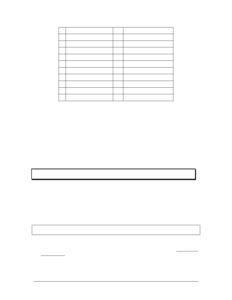
Pin
Function
Pin
Function
13 Ent 2 Input (Rt)
P
Pass 6 Mic Hi
14 Ent 2 Input (L)
R Ent 2 Audio Lo
15 Ent. 1 Input (Rt)
S
Pass 7 Mic Hi
16 Ent. 1 Input (L)
T Ent 1 Audio Lo
17
ALT Pass HP Right
U
Pass 8 Mic Hi
18 PA Activate
V Mute 2
19
ALT Pass Phones Left
W
ICS PTT Enable
20
Pilot CVR Output
X
Pilot ICS PTT
21
Copilot CVR Output
Y
Copilot ICS PTT
22
CVR Audio Lo
Z
ICS PTT Ground
Table 2-2 PMA7000H J2 Top Connector Pin Assignments (bold type indicates special pins for
PMA7000H)
2.9
Post Installation Checkout
After wiring is complete, verify power is ONLY on pin 20 of the J1 (bottom connector), and airframe
ground on bottom connector pin Z. Failure to do so will cause serious internal damage and void PS Engi-
neering's warranty.
2.10
Unit Installation
To install the PMA7000H, gently slide the unit into the mounting rack until the hold-down screw is en-
gaged. While applying gentle pressure to the face of the unit, tighten the 3/32" hex-head in the center of the
unit until it is secure. DO NOT OVER TIGHTEN.
Warning: Do not over-tighten the lock down screw while installing the unit in tray.
Internal damage will result.
2.10.1 Required Test Equipment
In order to return an aircraft to service after installation of the PMA7000H, the installer must have access to
a Marker Beacon signal generator:
a.
IFR NAV401L, NAV402AP, IFR4000
b.
TIC T-30D, T-36C
Equivalent test equipment is acceptable as long as the testing requirements can be met.
2.10.2 Operational Checkout
NOTE: The IntelliVox® is designed for ambient noise levels of 80 dB or above. Therefore some clipping
may occur in a quiet cabin, such as without the engine running, in a hangar. This is normal.
1. Apply power to the aircraft and avionics.
2. Plug headsets into the pilot, copilot, and occupied passenger positions.
3. Verify fail-safe operation by receiving and transmitting on com 1 from the pilot position, with the audio
panel power off. The Com audio will be present in the right ear cup only.
4. Verify that unswitched audio is present in right ear cup.
5. Switch on the unit by pressing the volume (VOL) knob.