Carrier AQUASNAP 30MPA User Manual
Page 8
8
NO
TES:
1.
Chil
ler
m
u
st
b
e insta
lled
le
v
e
l to maintain
proper comp
ressor oil retur
n
.
2.
Wir
ing an
d pip
ing sho
w
n
are gen
er
al po
ints-of-
co
nnect
ion gu
ides only
and are
not in
tended f
o
r a sp
e-
cific installation. Wir
ing and piping sho
w
n are f
o
r a
q
uic
k
o
v
er
vie
w
of
system and are not in accordance
with recogniz
e
d
stan
dards
. Units
should
b
e installed using ce
rt
ified dr
a
w
ings
.
3.
All wir
ing m
u
st comply
with a
pplica
b
le lo
cal and national codes
.
4.
All piping m
u
st f
o
llo
w
standard
p
iping tech
ni
q
ues
. Ref
e
r
to
Ca
rr
ier System Design
Man
ual or appropr
i-
ate ASHRAE (Amer
ican Society of Heating, Re
fr
iger
ating, and Air Cond
itioning E
n
ginee
rs) hand
b
ook
fo
r d
e
ta
ils
.
5.
See T
a
b
le
s 1A and 1B f
o
r minim
u
m system fluid v
o
lum
e
. This system ma
y re
q
uire the addition of a
holding t
ank to
ensu
re ade
q
u
a
te v
o
lume
.
6.
A
str
a
iner with a minim
u
m of 40
m
e
sh m
u
st
b
e
installed within 10 ft (3
m) of
th
e
e
v
apor
ator fluid inlet to
pre
v
ent d
e
b
ri
s from clogging or damaging the
hea
t e
xchanger
. T
h
is
str
a
iner is
re
q
u
ired and
is
a
v
aila
b
le
as an accessor
y.
7.
Piping, wir
ing, s
w
itche
s
, v
ents
, str
a
iners
, dr
a
ins
, and vi
b
ra
tion
isolation a
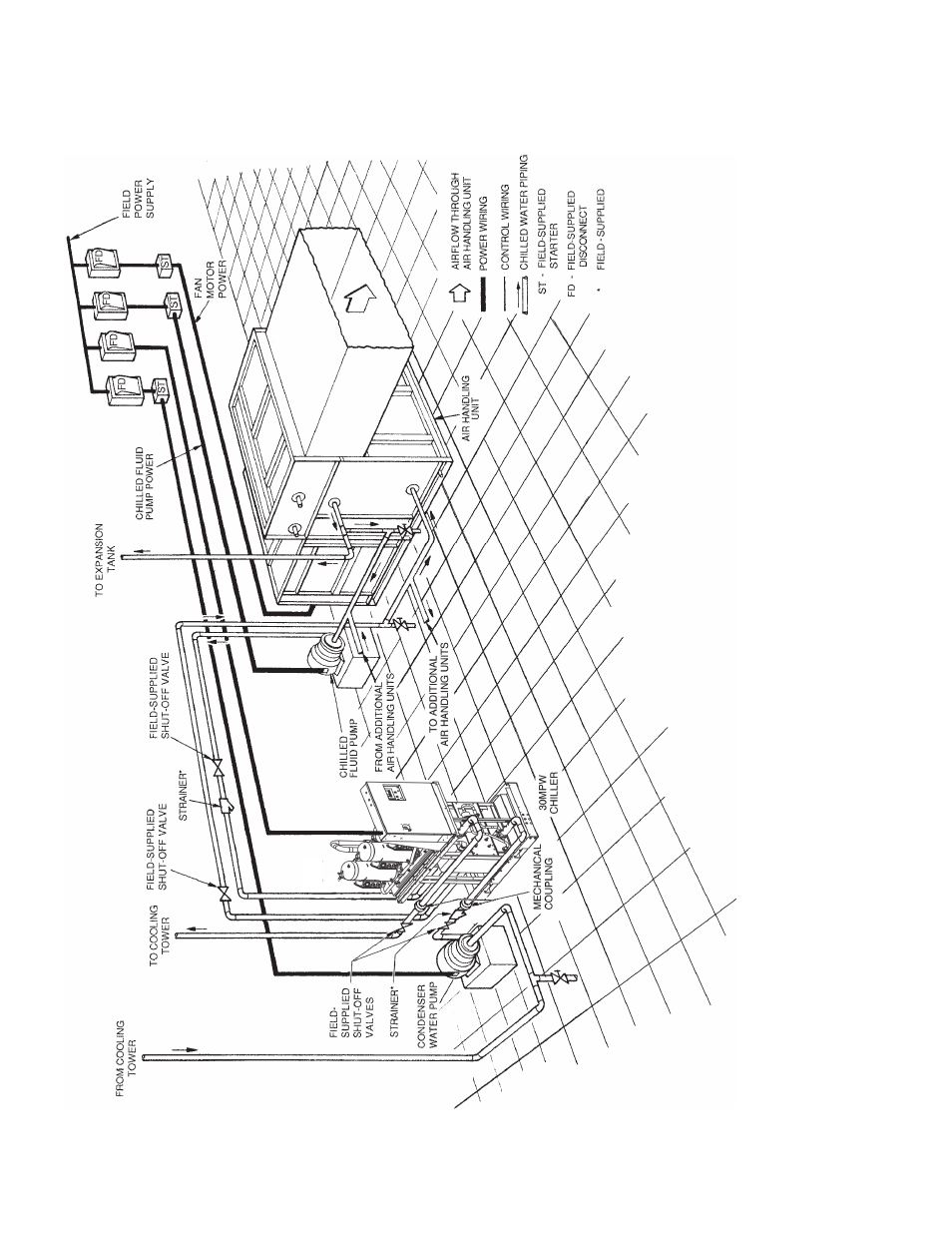
re all field-supplied.
Fig. 8 — T
y
p
ic
a
l
Piping wit
h
Liq
u
id-Coole
d
3
0
MPW
Ch
iller
a30-4997