Figure 2-4 – Cisco CRS-1 User Manual
Page 27
2-7
Cisco CRS Carrier Routing System 8-Slot Line Card Chassis Site Planning Guide
OL-5802-09
Chapter 2 Power and Cooling
DC Power Systems
Note
DC input power cables must be connected to the PDU terminal studs in the proper positive
(+) and negative (–) polarity. In some cases, the DC cable leads are labeled, which is a
relatively safe indication of the polarity. However, you must verify the polarity by measuring
the voltage between the DC cable leads. When making the measurement, the positive (+)
lead and the negative (–) lead must always match the (+) and (–) labels on the PDU.
•
An earth ground cable is required for each fixed configuration DC PDU. We recommend that you
use at least 6-AWG multistrand copper wire. This wire is not available from Cisco Systems; it is
available from commercial cable vendors.
The ground wire cable lug should be dual-hole, as shown in
, and able to fit over M6
terminal studs at 0.625-inch (15.88-mm) centers (for example, Panduit part number LCD6-14A-L
or equivalent).
Figure 2-3
DC Earth Ground Cable Lug
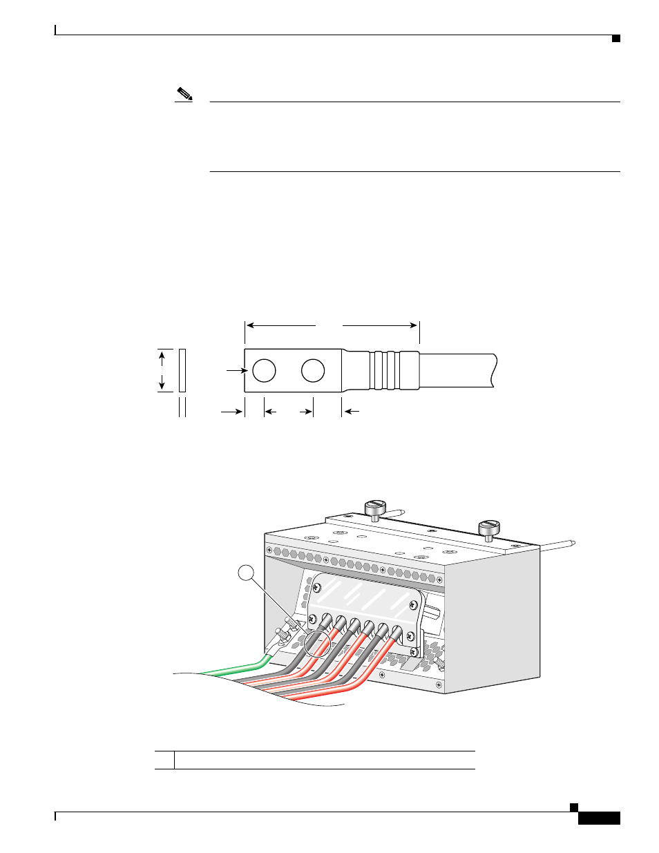
shows the DC input power cables connected to the DC PDU terminal studs.
Figure 2-4
Fixed Configuration DC PDU Power Cable Connections
Crimp area
25527
2.24
0.48
0.08
0.25
0.37
0.63
End View
Ø 0.267
2 holes
All measurements in inches
1
Each set of cables (RTN and –48V/–60V) is a single VDC input.
129533
1