OFM 1007M User Manual
Retro bench, Assembly instructions
Assembly Notes:
During assembly, hand tighten screws only. When all screws
are in place, you may then tighten all screws completely.
CAUTION:
1. Check for loose screws and tighten them every 6 months.
Models 1006M / 1007M
Retro Bench
WEIGHT CAPACITY: 500 lbs. Per Bench
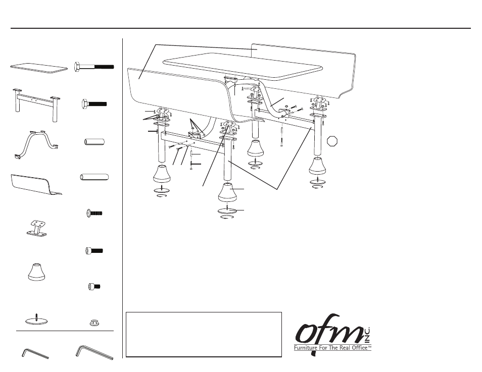
Parts Listing
STOP
Assembly Instructions
Tools Needed: Adjustable Pliers, Allen Wrench
Please read all instructions before assembly.
Step 1: Slide Post Covers (F) over legs of
H-Frames (B) as shown.
Step 2: Screw in Anchoring Plates/Leveling
Glides (G) to bottom of H-Frame legs (B).
Step3: Align holes in H-Frames (B) with the
corresponding holes in the Cross Bar (C).
Insert 10x75mm Bolts (H) through the 56mm
Bolt Sleeves (K) and into the 10mm Nuts (O)
for vertical connections. Insert 10x55mm
Bolts (I) through 36mm Bolt Sleeves (J) into
the Nuts (O) for horizontal connections.
Tighten with Allen Wrench and Pliers.
Step 4: Align Bench Brackets (E) with H-Frames (B)
and attach using 10x25mm Screws (M)
and 10mm Nuts (O). Tighten with Allen
Wrench.
Step 5: Align Benches (D) with Bench Brackets (E)
and attach using 8x12mm Screws (L).
Tighten with Allen Wrench.
Step 6: Align Table Top (A) with Cross Bar (C)
and attach using 10x12mm Screws (N).
Tighten with Allen Wrench.
919-362-4765 (fax)
www.ofminc.com
161 Tradition Trail, Holly Springs, NC 27540
800-520-7471 (voice)
919- 303-6389 (voice)
[email protected]
09.10.2010
G
Anchoring Plate/Leveling Glide
with Anti-Skid Rubber Pad
4 Units
F
Post Covers
4 Units
C
Cross Bar
1 Unit
B
H-Frames
2 Units
A
Table Top
1 Unit
E
Bench Brackets
4 Units
D
Benches
2 Units
K
56mm Bolt Sleeve
2 Units
J
36mm Bolt Sleeve
4 Units
H
10x75mm Bolt
2 Units
M
10x25mm Screw
8 Units
L
8x12mm Screw
16 Units
O
10mm Nut
14 Units
N
10x12mm Screw
4 Units
I
10x55mm Bolt
4 Units
8mm Allen Wrench
1 Unit
5mm Allen Wrench
1 Unit
A
D
G
F
C
H
K
N
M
L
J
I
B
E
O
O