OFM 334 User Manual
Four unit beam seating, Assembly instructions, Parts listing
WEIGHT CAPACITY: 1,000 lbs.
Assembly Notes:
During assembly, hand tighten screw only when all screws
are in place, you may then tighten all screws completely.
CAUTION:
1. Do not use this chair as a step ladder.
2. Check for loose screws and tighten them every 6 months.
Parts Listing
Model 324 / 334
Four Unit Beam Seating
C
16 Units
(12 with table)
B
16 Units
(12 with table)
A
8 Units
(6 with table)
F
4 Units
E
4 Units
D
8 Units
I
2 Units
H
8 Units
H-1
16 Units
G
20 Units
(16 with table)
L
16 Units
(12 with table)
K-1
8 Units
J
8 Units
N
1 Unit
W
Beam Table
1 Unit (optional)
V
Seat Frame Mount
4 Units
M
1 Unit
P
Seating Beam
1 Unit
S
Seat Frame
4 Units (3 Units with table)
R
Seat Cushion
4 Units (3 Units with table)
Q
Beam Legs
2 Units
K
4 Units
(R)
(L)
J-1
8 Units
M-1
1 Unit
O
1 Unit
O-1
1 Unit
A
T/U
5
1
1
E
Q(R)
O-1
H
J
D
H-1
J-1
J
M
M-1
K-1
H-1
K
O
P
4
T
Stars Back
4 Units (324)(3 with table)
U
Moon Back
4 Units (334)(3 with table)
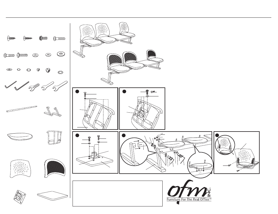
Assembly Instructions
Tools Needed: Phillips Head Screwdriver
Please read all instructions before assembly.
Step 1: Attach Seat Cushion (R) to Seat Frame (S) using screws (B)
and washers (L). Tighten screws with Philips head screwdriver.
Step 2: Attach Seat Frame Mount (V) to the Seat Frame (S) with 4
bolts (C) and washers (G), using wrench (N) that is provided.
Step 3: First place 2 washers (I) between Table (W) and Frame Mount (V)
on two back drill holes. Then attach Frame Mount (V) to Table (W)
with bolts (F) and washers (G), using Philips head screwdriver.
Step 4a: Place Beam Legs (Q) into open ends of Seating Beam (P).
Attach with bolts (E), small washers (J), large washers (H) and
nuts (K) as shown in diagram Step 4, using allen wrench (M)
that is provided.
Step 4b: Place Seat Frame Mount (V) and Seat Frame (S) onto Seating
Beam (P) and align holes. Attach with long bolts (D), small
washers (J-1), large washers (H-1) and nuts (K-1) as shown in
diagram Step 4, using allen wrench (M-1) that is provided.
Step 5: Place the plastic chair Back (T / U) onto top of Seat Frame (S).
Line up holes in the rear of the chair back and frame and connect
using two short screws (A). Tighten screws with Philips head
screwdriver.
3
F
G
I
W
V
F
G
Front
R
S
B
L
1
Model 324
Model 334
919-362-4765 (fax)
www.ofminc.com
161 Tradition Trail Holly Springs, NC, 27540
800-520-7471 (voice)
919- 303-6389 (voice)
[email protected]
06.02.2010
1
N
C
G
2
V
S