OFM 1005 User Manual
Group/cluster tables, Assembly instructions
Assembly Notes:
During assembly, hand tighten screws only. When all screws
are in place, you may then tighten all screws completely.
CAUTION:
1. Do not use this chair or table as a step ladder.
2. Check for loose screws and tighten them every 6 months.
Models: 1002 / 1003 / 1004 / 1005
Group/Cluster Tables
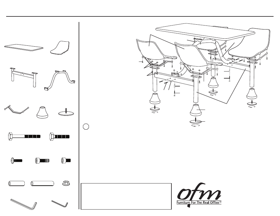
Parts Listing
STOP
Assembly Instructions
Tools Needed: 18mm Crescent Wrench, 15mm Crescent Wrench
Please read all instructions before assembly.
Step 1: Slide Post Covers (F) onto legs of H-Frames (C) as shown.
Step 2: Screw Leveling Glides (G) into the bottom of legs of the H-Frames (C).
Step 3: Align holes in H-Frames (C) with corresponding holes in the Cross Bar (D). Insert 10x75mm Bolt (H)
through 56mm Bolt Sleeve (N) and into aligned holes in H-frames (C) and Cross Bar (D). Secure
with 10mm Nut (O). Insert 10x55mm Bolt (I) through 36mm Bolt Sleeve (M) and into the aligned holes
in the H-Frames (C) and Cross Bar (D) as shown. Secure with 10mm Nut (O) using wrench.
Step 4: Align Seat Brackets (E) with H-Frames (C) and attach with 10x25mm Screw (K) and 10mm Nut (O)
using Large Allen Wrench (P) that is provided.
Step 5: Align Seats (D) with Seat Brackets (E) and attach with 8x25mm Screw (J) using Small Allen Wrench (Q).
Step 6: Align Table Top (A) with Cross Bar (D) and attach with 10x12mm Screw (L) using Large Allen Wrench (P).
161 Tradition Trail, Holly Springs, NC, 27540
800-520-7471 (voice)
919-362-4765 (fax)
919-303-6389 (voice) www.ofminc.com
[email protected]
01.03.2014
G
Leveling Glides
4 Units
F
Post Covers
4 Units
E
Seat Brackets
4 Units
B
Seat
4 Units
A
Table Top
1 Unit
C
H-Frames
2 Units
D
Cross Bar
1 Unit
N
56mm Bolt Sleeve
2 Units
M
36mm Bolt Sleeve
4 Units
H
10x75mm Bolt
2 Units
K
10x25mm Screw
8 Units
I
10x55mm Bolt
4 Units
J
8x25mm Screw
16 Units
O
10mm Nut
14 Units
L
10x12mm Screw
4 Units
P
Large Allen Wrench
1 Unit
Q
Small Allen Wrench
1 Unit
C
B
G
F
D
A
H
E
M
I
N
J
K
O
L
H
N