Model 1074, Warning, Installation instructions – Oberon 1074-06-VENT User Manual
Page 2
Step 7 – Once the telecom enclosure is
installed in the ceiling, run the power cable to
the
electric
junction
box.
The
junction
box/receptacle should be wired according to
electrical codes.
**IMPORTANT** - This procedure should
be done by a trained electrician.
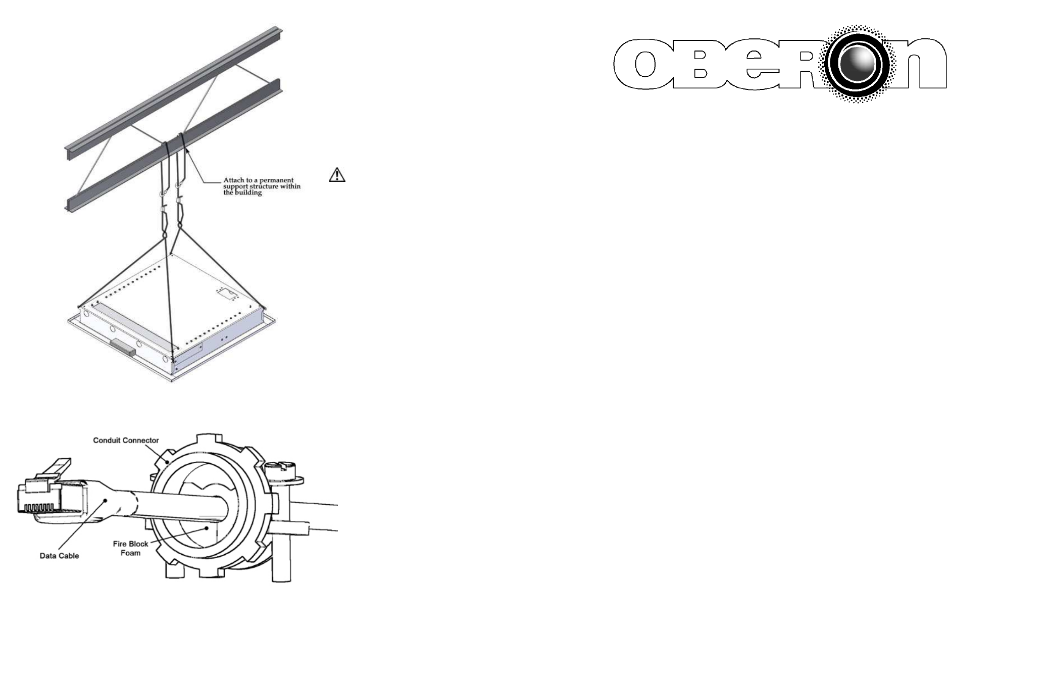
Step 8 – Run the data and power cable (if
required) through the conduit connectors
located on sides of the access point enclosure.
In order to maintain a separation of signal and
power, install the data and power cables
through opposite sides of the enclosure
utilizing the two knock-outs provided. Insert
foam into the conduit connector and pull the
data cable through far enough to allow
attachment to the access point (8" - 10").
Carefully tighten conduit connector around fire
block foam just enough to fill in gaps around
cable. Be careful not to over tighten and crush
the data cable(s), as this can affect cable
performance. Attach any additional data cables
as necessary and power up the networked
devices (these should be plugged into the
power
outlet
installed
in
the
telecom
enclosure).
Step 9 – Close and lock the access door. The installation is now completed.
Note: The Oberon Model 1074 telecom enclosure is specifically designed to be used with networking equipment no
bigger than 2U deep and 14” in length.
Page 4
MODEL 1074
Installation Instructions
**** WARNING ****
Please thoroughly read the product warning below
before installation to provide for a safe work
environment.
1. Ceiling mounted products should be installed in accordance with National Electric Code paragraphs 300.10 (Electrical
Continuity of Metal Raceways and Enclosures) and 300.11 (Securing and Supporting). Independent support wires or
other means must be used for the installation of this product in the ceiling. Acoustical, suspended, false, drop and
concealed spline ceiling grid work is not designed to support the weight of this product. Oberon’s ceiling mounted
products have four support wire tabs on the back box. These tabs shall be used for supporting the product with
independent support wires, wire rope, threaded rod, or other secure support means of adequate gauge and fire
resistance.
2. When closing the enclosure access door, be sure that the cam lock is completely engaged to prevent the access door
from accidentally swinging open.
3. When opening the enclosure door, be sure to support the door to prevent the door from accidentally falling open.
4. This enclosure has a maximum operating ambient of 55º C (131º F), the temperature within the enclosure may not
exceed this temperature, depending on power dissipation within enclosure.
5. A minimum air clearance of 1“ between the housing of the access point and the enclosure side walls must be
maintained for the safe operation of the equipment.
6. This product is intended to be installed by trained personnel.
7. Only Listed ITE products and Listed AC Receptacles shall be installed within the enclosure.
8. This product is to be repaired by personnel trained by the manufacturer or returned to the manufacturer for repair or
replacement.
9. Maximum weight to be installed in the unit is 44 lbs.
10. All knockouts, openings, and holes shall be sealed with a plug constructed of metal, or a non-metal material that
complies with UL 2043 or UL 1479.
11. All unused mounting holes should be sealed with tape or other material that complies with UL 1479.
12. If AC power is used inside the enclosure, ground the enclosure via the grounding means provided by the junction box
and AC receptacle.
Page 1
Figure 8
–
Tighten cable clamp around
foam fire block so that there are no air
gaps. Be careful not to over tighten and
crush the Ethernet cable(s).