Installation instructions, Model number 1065-ccoap – Oberon 1065-CCOAP User Manual
Page 2
Installation Instructions
Model Number 1065-CCOAP
(877) 867-2312 • www.oberonwireless.com
REV 1 9/11/2014
Oberon, Inc. •••• 1315 South Allen Street •••• State College, PA 16801
Copyright 2014
Assembly Components:
- Ceiling AP mount, Model 1065-CCOAP assembly – 1 each
- Recessed Retaining Bracket – 1 each
- #8-32 Screws – 4 each
- #8-32x1/4" Standoffs – 4 each
- Keys for access door lock – 2 each
- 8" Cable tie - 1 each
- Firestop Grommet – 1 each
- 1” Trade Size Conduit Connector – 1 each
- Support Wire – 4 each
If any of these items are missing, contact your Oberon representative.
Find a flat work surface to assemble the ceiling AP mount and access point
prior to mounting in ceiling.
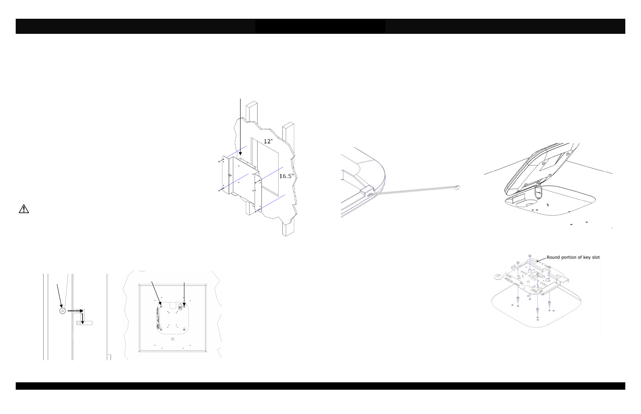
Step 1 – Make a 16.5" x 12" rectangular cutout within the wall or hard lid
ceiling. Mount the enclosure bracket so the mounting holes on the back surface
are on the top half with the open side facing up, and leave sufficient space
above the bracket for the conduit connector and any data/power cables (if
required). If possible, fasten the bracket to studs/joists using four #10 screws
that are at least 2" long. If no permanent structure is available, larger through
holes are available for use of anchors or other suitable hardware to fasten the
bracket (refer to Figure 1). If mounting in the ceiling, use the provided support
wire to secure the bracket to a permanent structure as well (refer to Figure 1).
**IMPORTANT** - This is an important safety feature that could
prevent human injury or damage to the access point should the unit
become dislodged from the ceiling.
Step 2 – Run the data and power cable (if required) through the conduit
connector located on the top face of the access point enclosure, then install the
enclosure by aligning the shoulder screw through the guide slots so the self
captured screws align with the nuts on the bracket. Tighten the self captured
screws in the back of the enclosure to the mounting holes in the enclosure
bracket (refer to Figure 2).
Step 3 – Install the Cisco
mounting plate using four (4) #8-
32
pan
head
screws.
The
mounting plate should be placed
so that the round portions of the
key slots are located closest to the
enclosure lock (refer to Figure 3).
The Cisco “BRACKET 2” should
be used with all Cisco 1400, 1600,
2600, 3500, 3600 and 3700
Access Points.
Page 2
NOTE: When using Cisco 3600 and 3700 series access points, mount the access point mounting plate directly to the
enclosure’s mounting plate. When using Cisco 1140, 1600, 2600, and 3500 series access points, you will need to use
the optional standoff kit to have the access point set at the proper height in the enclosure. The standoff kit is Oberon
P/N 39-STANDOFF.
Step 4 – Clip the provided fire stop grommet on to the data and power cable inside the enclosure, and slide the grommet into
the conduit connector so the end is flush with the connector
Step 5 - Optional safety tether: To attach the optional safety tether, insert the included cable tie into the Kensington lock slot at
an angle toward the top of the access point. There is an opening that will allow the cable tie to pass through (reference Figure
4).
Step 6 - Loop the cable tie through the tether anchor located on the mounting plate of the enclosure and lock the cable tie
loosely (reference Figure 5).
Step 7 – Attach data and power cables to the access
point from the front side of the AP mount.
Step 8 – Insert the key into the lock and turn the lock
180° in both directions to determine which way the
slide needs to be moved so that the mounting plate
is located furthest from the key lock.
NOTE: Cisco Access Points are locked into the AP
mount using the key. The turning of the key
activates a cam mechanism that slides the mounting
plate underneath the access point, thus, locking the
feet of the access point into keyhole shaped slots
located on the mounting plate. Once the access
point is installed and the key removed, the access
point is securely mounted in the AP mount and
cannot be removed without the key. Additional
security
measures
as
described
in
Cisco’s
Installation Guide (i.e. padlocks. security screws,
and security hasp) are not required.
Page 3
Figure 3 – Cisco Bracket 2 install, refer to note for using standoffs
Figure 4 – Insert cable tie through Kensington lock slot
Figure 1 – Cutout with Bracket
Figure 2 – Self Captured Screws
Self Captured Screws
Figure 5 - Loosely attach the cable tie
Support Wire Anchor Points
Shoulder Screw