Installation instructions – Oberon 1068-00 User Manual
Page 2
Installation Instructions
Model Number 1068-00
(877) 867-2312
www.oberonwireless.com
Rev. 06/19/2012
Oberon, Inc.
1315 South Allen Street State College, PA 16801
Copyright 2012
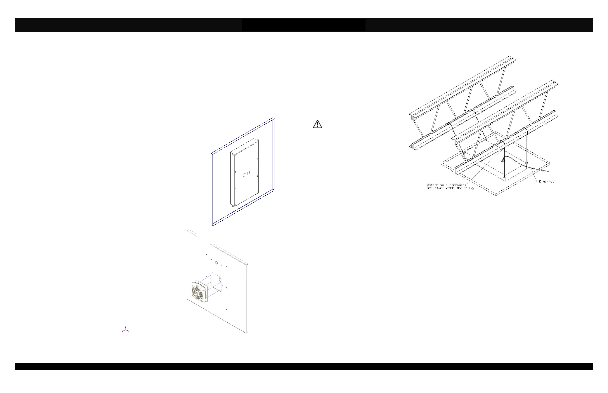
Figure 3 - Installation of grid wires and Ethernet cable.
Assembly Components:
- Universal Ceiling AP mount, Model 1068-00 assembly – 1 each
- Keys for access door lock – 2 each
- Grid Wire – 4 each
- Fire Resistant Foam – 1 each
- 3/4” Trade Size Cable Clamp – 1 each
- Support wire – 4 each
- Fire Block Foam – 1 each
If any of these items are missing, contact your Oberon representative.
*NOTE: The 1068-00 enclosure requires a unique mounting plate
for each access point. The mounting plate is purchased separately
based on the access point being used.
ITEMS TO NOTE:
Item 1 – The back side of the enclosure has a knockouts that will
accommodate either a cable clamp or a Keystone Jack (purchased separately)
that will be used to bring in the Ethernet cable (Reference Figure 1).
Item 2 – Each corner of the back box has a tab with a hole through it. These
tabs are to be used to attach the enclosure to a permanent structure within the
ceiling using grid wire (provided) or other connecting devices.
Item 3 –The enclosure requires a mounting plate (purchased separately) that
matches the access point being used. For example, the Cisco 3500 AP would
require the use of a Cisco 3500/3600 (Oberon P/N 68-3500/3600) mounting
plate, and an Aruba AP135 would require the use of an Aruba AP 135 (Oberon
P/N 68-AP135) mounting plate.
Item 4 – To attach the access
point/mounting plate assembly, place the
key in the lock and turn it counter
clockwise (note that the key may already
be turned as far as it will go). There are
four ¼” openings on the front surface of
the enclosure, verify that the sliding plate
below is positioned so that you can see
the round hole at the end of the slot in the
opening.
Item 5 – Each mounting plate has four
keyway studs located on the bottom that
will fit into the four ¼” openings on the
front of the enclosure. Align the keyway
studs with the openings and guide the
mounting plate into place. To lock the
access point/mounting plate assembly in
place, turn the key 180° clockwise.
(Reference Figure 2)
Page 2
CEILING INSTALLATION
Step 1 – Remove the ceiling tile
and replace it with the completed
AP mount assembly.
Step 2 – Use minimum 12-gauge
grid wire to attach the AP mount
to the ceiling. Attach one end of
the wire to the eye tabs and the
other end to a permanent
structure within the ceiling such as
a ceiling joist.
**IMPORTANT** - This is an
important safety feature that
could prevent human injury or
damage to the access point
should the unit become
dislodged from the ceiling.
Step 3 – Run the data and power
cable (if required) through the
conduit connectors located on
sides of the access point
enclosure. In order to maintain a
separation of signal and power,
install the data and power cables
through opposite sides of the
enclosure utilizing the two knock-
outs provided. Insert foam into the
conduit connector and pull the data cable through far enough to allow attachment to the access point (8" - 10"). Carefully
tighten conduit connector around fire block foam just enough to fill in gaps around cable. Be careful not to over tighten and
crush the data cable(s), as this can affect cable performance.
Step 4 – Attach the Ethernet cables to the access point from the front side of the AP mount.
NOTE: The access point/mounting plate assembly is locked into the ceiling mount using the key. The turning of the key
activates a cam mechanism that slides the mounting plate underneath the access point, thus, locking the slotted bosses
located on the bottom of the mounting plate. Once the access point/mounting plate assembly is installed and the key
removed, the access point is securely mounted in the ceiling mount and cannot be removed without the key. Additional
security measures (i.e. Kensington lock, etc.) are not required.
Page 3
Figure 2 – Close-up showing installation of the access point attached to the Oberon
mounting plate
Figure 1 – Back of 1068-00 enclosure