Installation instructions, Model number 1052-ccoant – Oberon 1052-CCOANT User Manual
Page 2
Installation Instructions
Model Number 1052-CCOANT
(877) 867-2312 • www.oberonwireless.com
P/N 1507 – Rev. 05/10/12
Oberon, Inc. •••• 1315 South Allen Street •••• State College, PA 16801
Copyright 2009
Assembly Components:
- Ceiling enclosure Model 1052-CCOANT assembly – 1 each
- ¾” Trade size conduit connectors – 1 each
- Fire Block Foam – 1 each
- #8 – 32 screw – 4 each
- #6 – 32 screw – 4 each
- Support wire – 4 each
- Installation Instructions – 1 each
- Keys for access door lock – 2 each
If any of these items are missing, contact your Oberon representative.
Find a flat work surface to assemble the ceiling enclosure, access point and antenna(s) prior to mounting in ceiling.
Step 1 – Place the ceiling enclosure
assembly on the work surface with the
keyed doorway unlocked. Remove hole
knock outs located on the outside edge of
the back box to install conduit connectors.
Install one conduit connector if using
P.O.E. or install 2 conduit connectors if
bringing in power and Ethernet and power
separately (Figure 1).
Figure 1
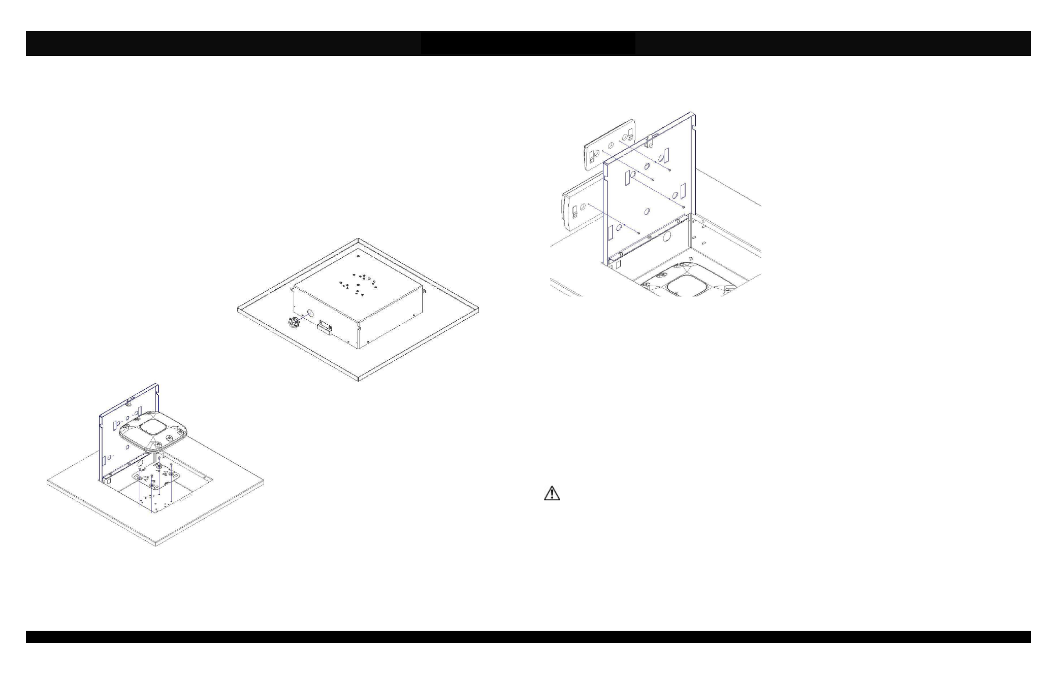
Step 2 – Install the access point so that the door is to the
left when the access point is upright. Securely fasten the
Cisco AIR-AP-BRACKET-1 to the mounting holes on the
back wall of the enclosure using (4) # 8-32 screws. Attach
the screws to the outter hole pattern. Attach the Access
Point to the mounting plate. Proceed to Step 3 (Figure 2).
Figure 2a
Page 2
Step 2 – Install Cisco 2.4 GHz and 5 GHz antennas by inserting
the connectors and cables through the .700” dia. holes in the
cover. The antennas should be installed so that the open ends of
the T-Bar clips on the antennas are facing toward the hinge of the
enclosure. After the cables have been pulled through the door,
use the #4-40 screws to connect the antennas (Figure 3).
Figure 3
The assembled unit is now ready for ceiling installation.
Step 4 – Remove the ceiling tile and replace it with the completed access point enclosure assembly.
Step 5 – Use minimum 12-gauge support wire (included) to support the access point enclosure independently of the ceiling
grid. Attach one end of the wire to the support wire tabs located along the edge of the back box and the other end to a
permanent supporting structure within the ceiling such as a ceiling joist (Figure 4).
**IMPORTANT** - This is an important safety feature that could prevent human injury or damage to the access
point should the unit become dislodged from the ceiling.
Page 3