3 modules, 4 hydraulics – NORAC UC5-BC-ECHO-VT User Manual
Page 47
43
15.3 Modules
The green LED on the module is flashing:
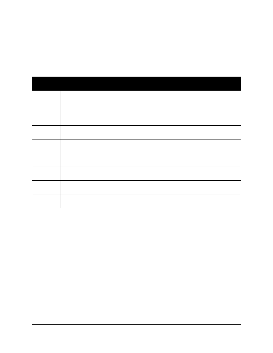
Count the number of times that the LED flashes and refer to the following table for
diagnostic. The LED will flash quickly followed by a three second delay, after which the
flash pattern will be repeated. Display Bus errors are only valid on the Control Module.
LED
Pattern
Description
Solid
Green
UC5 module is operating correctly.
1 Blink
Module is not communicating with any other modules on the Display (ISO)
CANbus.
2 Blinks
Module is not communicating with any other modules on the NORAC CANbus.
3 Blinks
The module has disabled the Display CANbus communication because there
were too many errors on the CANbus.
4 Blinks
The module has disabled the NORAC CANbus communication because there
were too many errors on the CANbus
5 Blinks
There are CANbus errors on the Display Bus, but the module is able to
continue communicating
6 Blinks
There are CANbus errors on the NORAC CANbus, but the module is able to
continue communicating
7 Blinks
There are CANbus errors on the Display Bus, but the module is able to
continue communicating
8 Blinks
There are CANbus errors on the NORAC CANbus, but the module is able to
continue communicating
15.4 Hydraulics
When diagnosing hydraulic problems you should first determine if the electrical system is
ok. Check all cable connections and ensure they are tight and free of corrosion. Measure
the electrical output at the valve to ensure there is voltage at the connection.
Most valves will have an override pin. This is a small brass colored hole located at the end
of each coil in the center. There will be one for each valve. By pushing in the pin you can
manually activate the valve. There must be pressure at the block for the function to move.
If your sprayer is equipped with a bypass valve it must be activated anytime a hydraulic
function is required.