8 module installation, 1 control module – NORAC UC5-BC-HG03 User Manual
Page 19
16
8 Module Installation
An optional module mounting bracket kit is available for purchase from NORAC. The
mounting brackets are compatible with control modules and input modules. One kit is needed
per module.
Item
Part Number
Name
Quantity
B20
43708
UC5 MOUNTING BRACKET KIT (CONTROL AND INPUT MODULES)
1
8.1
Control Module
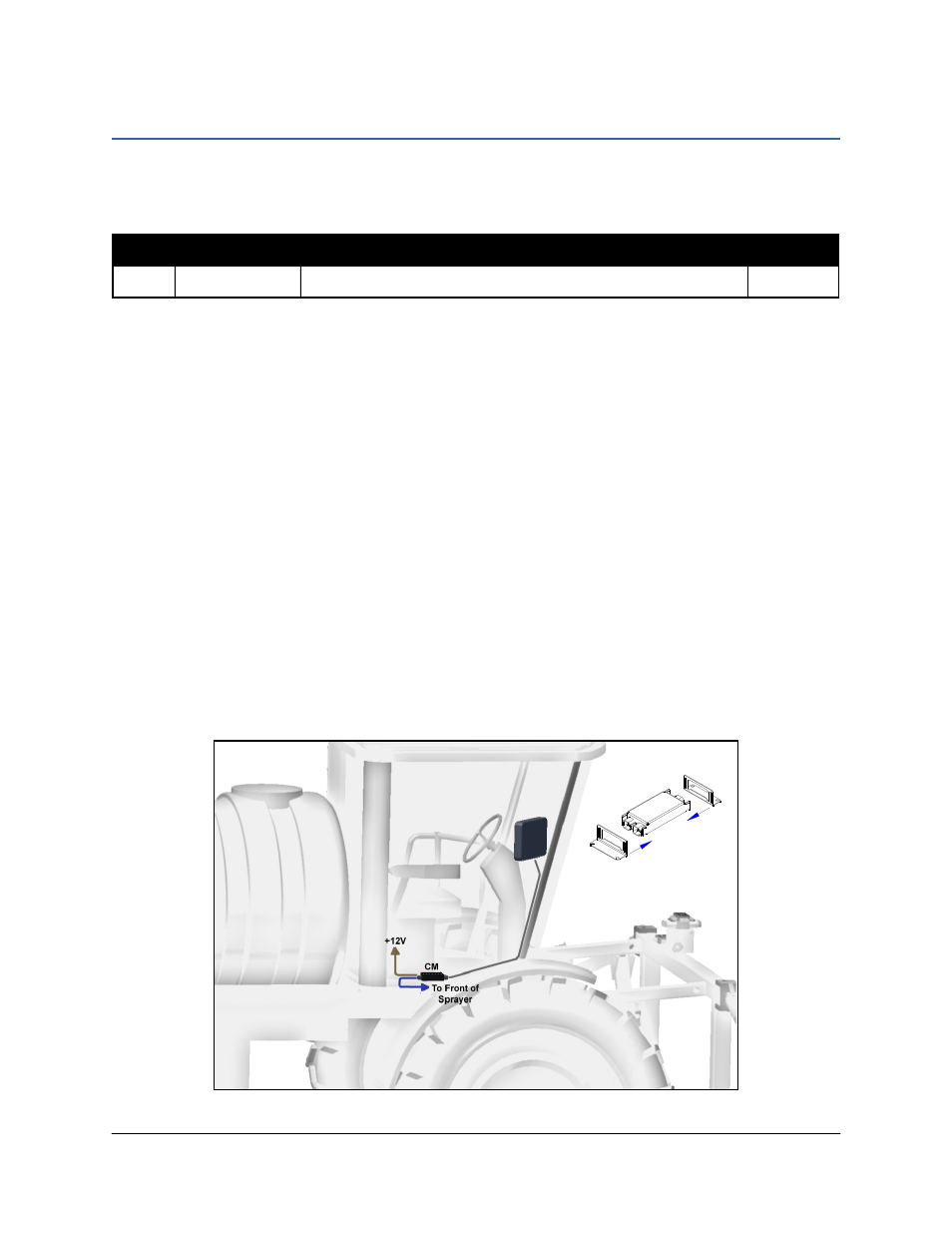
1. Refer to Figure 2 and Figure 15.
2. Securely mount the control module (E01) with the lowest serial number inside the sprayer
cab, using screws, cable ties or optional brackets.
3. Connect cable C21 between the control module and the display cable. Cable C21 must be
connected to the end of the control module with only one Deutsch connector.
4. Connect the power cable (C30) to one of the two CANbus connectors on the control
module. Be sure that the power is connected to a switched power supply.
5. Route cable C01 from the other CANbus connector to the cab knock outs.
6. Connect cable C03 to cable C01 at the cab knock outs.
7. Connect a 3-way coupler (E10) between cable C03 and cable C09. Connect cable C09 to
cable C04. Route cable C04 towards the valve block.
Figure 15: Control Module Mounting