6 hydraulic installation, 1 valve assembly – NORAC UC4+BC+GV1 User Manual
Page 21
19
4.6 H
YDRAULIC
I
NSTALLATION
WARNING!
The hydraulic system creates very
high pressure. Before disconnecting
any hydraulic lines ensure all pressure
has been bled from the system.
When changing the boom hydraulic
hoses leave the booms in
TRANSPORT POSITION.
IMPORTANT:
Component failure due to oil
contamination is not covered under
the UC4+ Spray Height Control
system warranty. It is recommended
that a qualified technician does the
hydraulic installation.
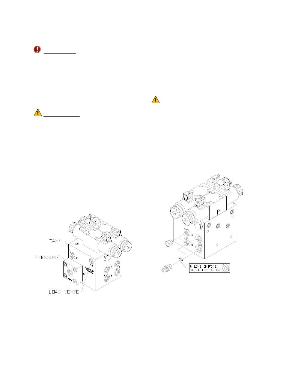
4.6.1 Valve Assembly
1. On a clean surface remove all plastic
plugs from the NORAC hydraulic Valve
(V01) (Figure 20).
Figure 20: NORAC Valve Block
2. Install the 6MB-6MJ fittings (F02) on the
"P" and "T" ports and tighten to 18 ft-
lbs.
3. Install two orifices (F04) into the "B"
ports with the notch facing outward
as shown in Figure 21.
You must ensure there are no
other orifices present in the
circuit between the NORAC
valve block and the boom
cylinders
4. Install the 6MB-4MJ fittings (F06) into
the "B" ports and tighten to 18 ft-lbs.
5. Install the 6MBP (F03) into the “A”
ports and tighten to 18 ft-lbs.
Figure 21: Valve Block Assembly