5 roll sensor installation – NORAC UC4+BC+GV1 User Manual
Page 16
14
4.5 R
OLL
S
ENSOR
I
NSTALLATION
When mounting the roll sensors, be
sure they cannot contact any parts of
the boom or frame.
Mount the roll sensors to the included roll
sensor brackets using the machine screws
and nylon lock nuts, as illustrated in Figure
13.
The roll sensors must be
mounted tightly to the brackets.
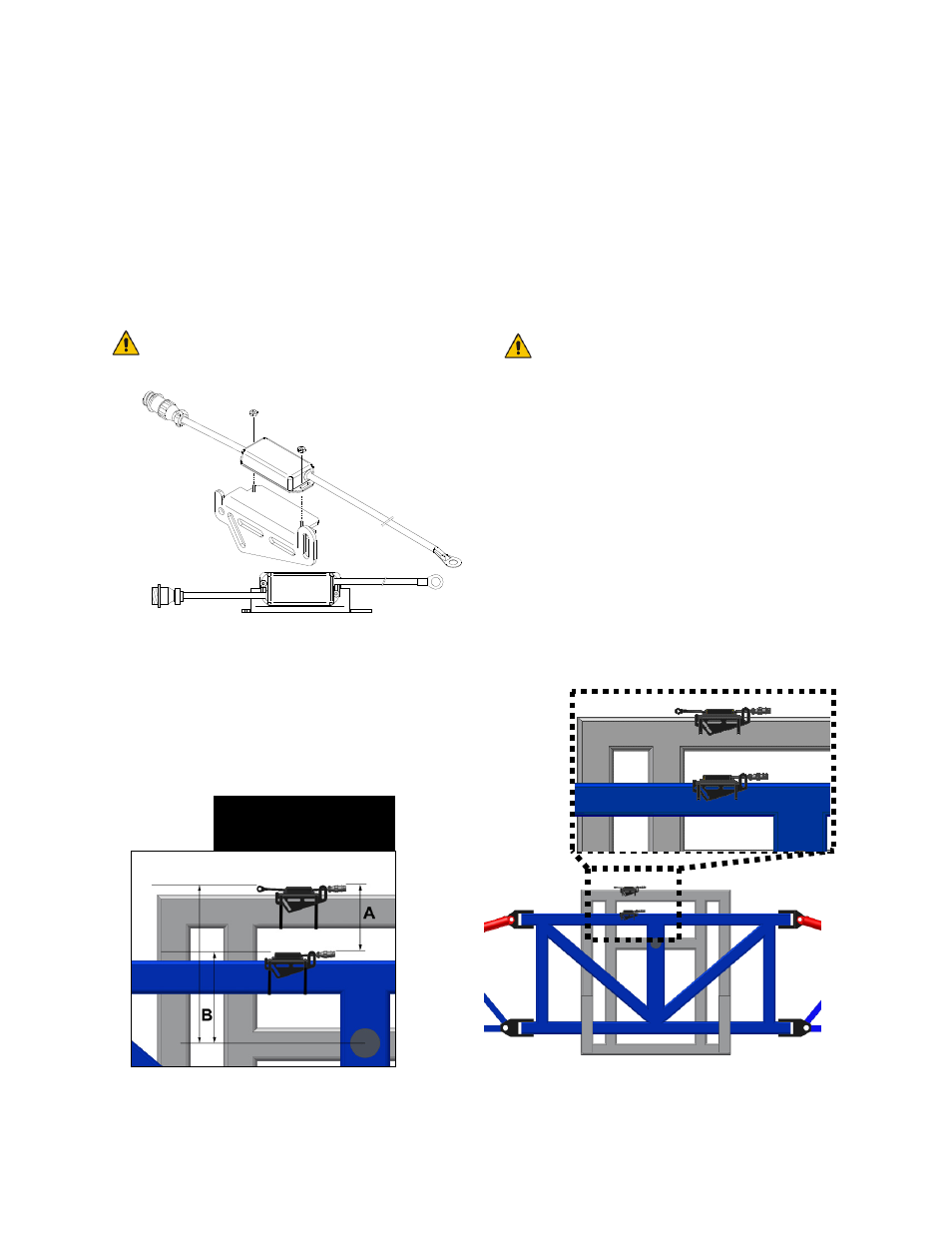
Figure 13: Mounting the Roll Sensor
to the Roll Sensor Mounting Bracket
When mounting the roll sensors use the
following guidelines and refer to Figure 14.
a) The intermediate frame roll sensor
must have the lowest serial number and
the chassis roll sensor must have the
highest serial number.
b) The smaller the distance between A and
B in Figure 14, the better the
performance will be.
Distance A cannot be more than
12”.
c) The roll sensors must not be mounted
below the pivot point.
d) Ensure the roll sensors are sitting
relatively level when the sprayer chassis
and boom are level.
e) All roll sensors must be mounted with
the circular AMP connector facing
towards the Right-Hand Wing (when
looking from the rear of the sprayer).
f) It is recommended that you mount the
roll sensor on the left hand side of the
boom.
Figure 14: Mounting Guidelines for Roll Sensor
Connectors towards
Right-hand Wing