NORAC UC4+BC+GM1 User Manual
Page 27
25
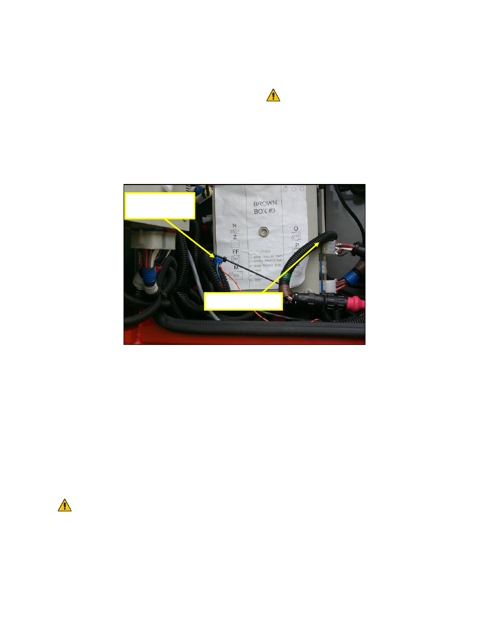
2. On the right-hand side of the cab there
is an electrical access panel. The tee
connection on the UC4+ power cable
(C10) must be connected between the
9-pin connector shown in Figure 31
and the electrical panel.
3. The free-hanging yellow wire from C10
must be electrically connected to the
light blue bypass wire in the main wire
harness that exits the rear of the access
panel (Figure 31). Use a multimeter to
ensure you have selected the right wire.
The light blue wire should have
12-Volts on it whenever one of
the boom LIFT switches is
operated. Use a tee electrical
connector as shown (not
provided) or solder and seal
appropriately.
Figure 31: UC4+ Power Cable Connection
4. Connect the free hanging black wire on
C10 to a good electrical ground on the
sprayer.
5. Connect the 16-pin AMP plug on C10
to the UC4+ Control Panel (E01) in the
sprayer cab.
6. Connect the valve extension cable
(C04) to the 6-pin Tower connector on
C10.
The valve extension cable (C04)
may be packaged with one GP
end not installed. This is normal;
it helps installations for other
sprayer types. Pin this connector
on (connector included) as per
drawing in Section 5.5. TAKE
EXTRA CARE! These pins
require a special tool to remove
them if you make an error!
7. Connect one end of the UC4 trunk
cable (C01) to the UC4+ Control Panel
(E01).
8. Route C04 and C01 to the rear of the
sprayer where the NORAC hydraulic
valves are located.
9. Connect the 6-pin Tower on the UC4
Valve Cable (C03) to the 6-pin Shroud
on C04 at the rear of the sprayer
(Figure 33).
Bypass Valve
Connection
Tee Connection