3 hydraulic plumbing – NORAC UC4+BC+GM1 User Manual
Page 25
23
4.10.3 Hydraulic Plumbing
WARNING!
From this point in the installation the
booms will be inoperative until the
electronics are fully installed.
1. After the NORAC valves are mounted,
the hydraulic hoses and fittings can be
plumbed. The plumbing for the hydraulic
circuit is shown schematically in Figure
3.
2. Connect the NORAC supplied hoses
(H03) to the Pressure (P) and Tank (T)
ports on the NORAC valve block
(V01). Route both of these lines to the
sprayer valve block.
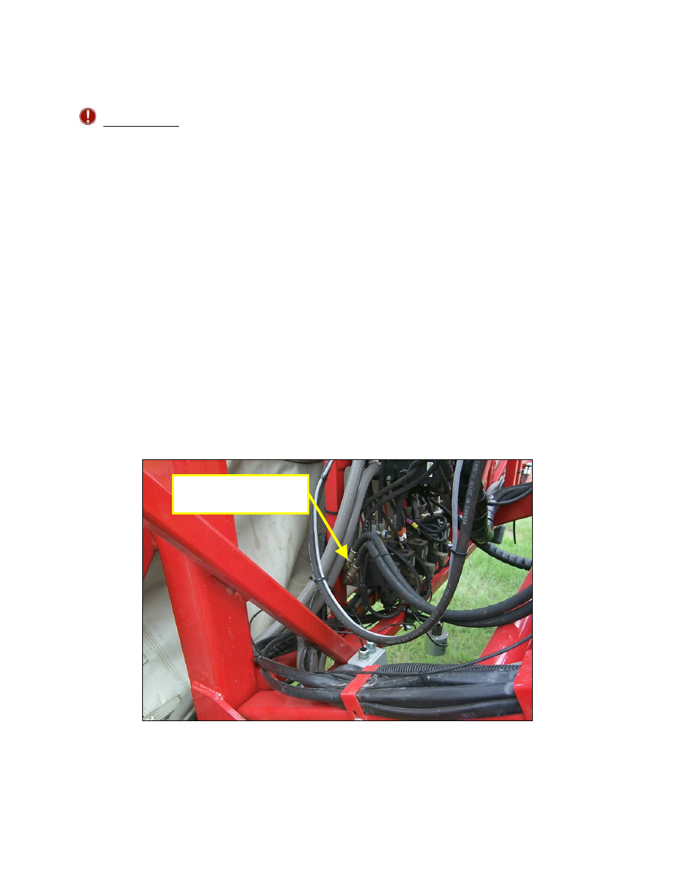
3. Connect H03 to the auxiliary Pressure
and Tank ports available on the side of
the sprayer valve block (Figure 28)
with the 10MB-6MJ couplings (F04).
4. The existing hoses that run to the boom
tilt cylinders should be disconnected
from the sprayer valve block and the
cylinders.
5. Connect NORAC supplied hoses
between the cylinders and NORAC
valve block. Items H04 are for the left
boom cylinder. Items H05 are for the
right boom cylinder.
a. The “raise” lines from the side of
the boom tilt cylinders, which raise
the booms, must be connected to
the "B" ports of the NORAC valve
block. The ports on the sprayer
block must then be plugged/capped
with Item F03.
b. The "A" ports of the NORAC block
must be connected to the “lower”
lines of the cylinders.
Figure 28: Auxiliary Pressure and Tank Connections
P
ressure and Tank
Connections