5 roll sensor installation – NORAC UC4+BC+CS5 User Manual
Page 18
16
4.5 R
OLL
S
ENSOR
I
NSTALLATION
Mount the roll sensors to the included roll
sensor brackets using the machine screws
and nylon lock nuts, as illustrated in Figure
15.
The roll sensors must be
mounted tightly to the brackets.
The chassis roll sensor bracket
requires the tabs to be cut off.
See Figure 20.
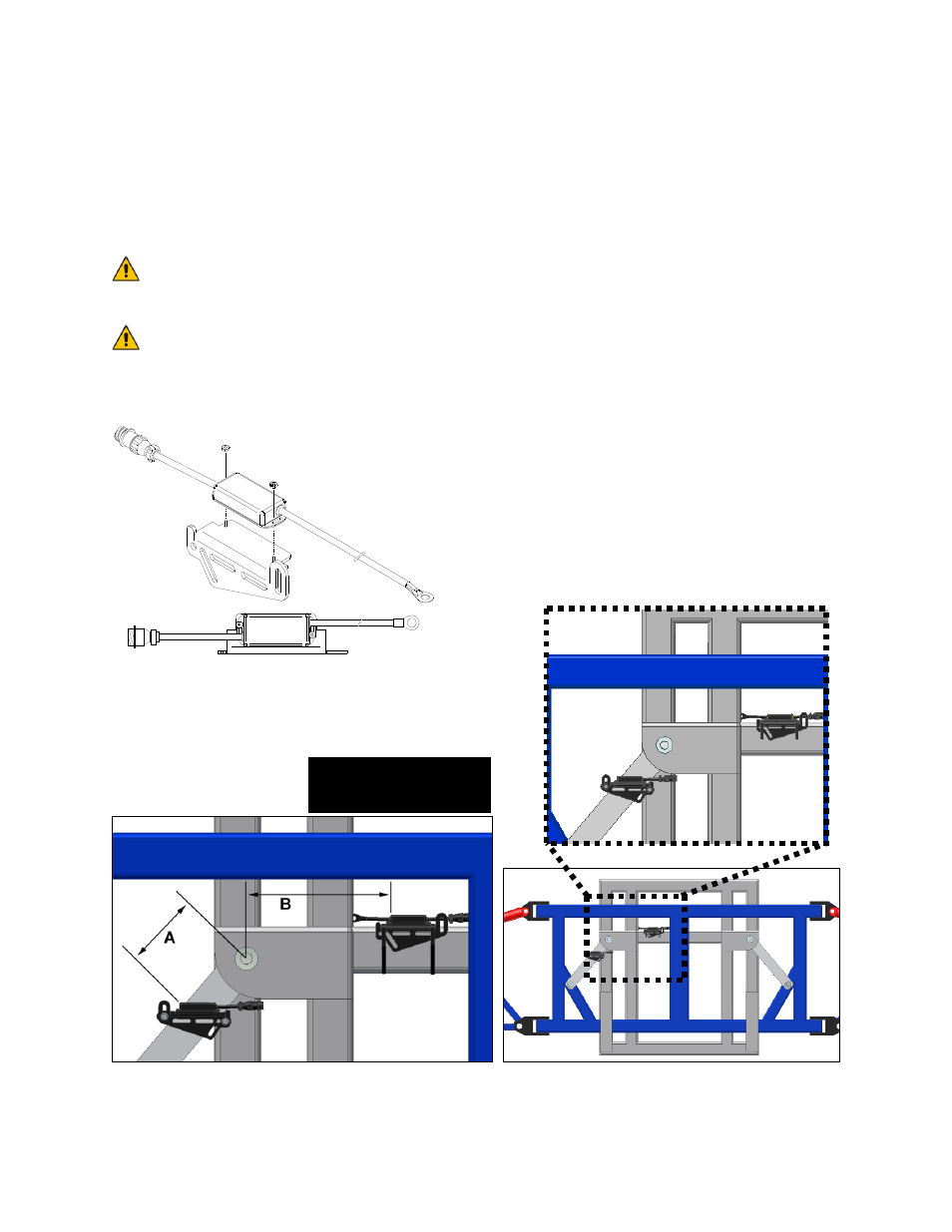
Figure 15: Mounting the Roll Sensor
to the Roll Sensor Mounting Bracket
When mounting the roll sensors, use the
following guidelines and refer to Figure 16.
a) The intermediate frame roll sensor
must have the lowest serial number and
the chassis roll sensor must have the
highest serial number.
b) The smaller the distance between A and
B in Figure 16, the better the
performance will be.
c) Ensure the roll sensors are sitting
relatively level when the sprayer chassis
and boom are level.
d) The roll sensors MUST be mounted
with the circular AMP connector
facing towards the Right-Hand
Wing (when looking from the rear of
the sprayer).
Figure 16: General Roll Sensor Mounting Location on a Trapeze Style Boom
Connectors towards
Right-hand Wing