4 hydraulic plumbing – single acting – NORAC UC4.5-BC-RA1 User Manual
Page 30
27
8.4 Hydraulic Plumbing – Single Acting
From this point on in the installation the booms will be inoperative until the
hydraulics are fully installed.
1. After the NORAC valves are mounted, the hydraulic hoses and fittings can be plumbed
following the schematic in Figure 3.
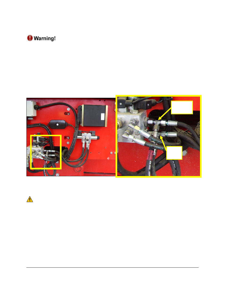
2. Connect pressure and tank hoses (*H01) to the P and T supply at the front of the sprayer
as illustrated in Figure 32. Run these hoses to the NORAC valve block. If the sprayer
does not have steering, these hoses may be connected directly to the RAU block (without
using tee pieces (*F05)).
Figure 32: “P” and “T” Connections (tee’d with steering “P” and “T” hoses)
3. Connect the “P” and “T” hoses to the NORAC valve block.
If “P” and “T” are connected backwards, no oil will flow though the NORAC
block.
4. Connect the “B” ports of the NORAC block to the wing raise lines by removing the wing
tilt hoses from the RAU block and fitting them to the NORAC block.
5. Close the ports of the RAU block tilt valves with caps or plugs. These valves are no longer
used after this installation.
Pressure
Tee
Tank
Tee