MUTEC MC-6 User Manual
Page 20
\\\\\\\\\\\\\\\\\\
A N H A N G
A N H A N G
A N H A N G
> > > > > > > > > > > > > > > > > > > > > > > > > > > > > > > > > > > > > > > > > > > > > > > > > > > > > > > > > > > > > > > > > > > >
> > > > > > > > > > > > > > > > > > > > > > > > > > > > > > > > > > > > > > > > > > > > > > > > > > > > > > > > > > > > > > > > > > > >
88
20
X-SRC
BI-DIR
UNI-DIR
AES3
S/P-DIF op
SRC
REFERENCE
88.2
48.0
44.1
32.0
192.0
96.0
176.4
MODE
AES3id
S/P-DIF co
AUDIO
IN
AES11
WCLK
AES3
S/P-DIF op
AES3id
S/P-DIF co
This setting is a very special and of course unique function of your MC-6!
The function allows to convert two digital audio signals at the same time,
whereas both conversion streams may consist of different sampling rates.
On this occasion, the MC-6 extracts the clock out of the two incoming digital
audio signals and uses these as clock references to synchronize the SRCs in
front of each of the format-same outputs. This is especially useful when
interconnecting two unsynchronized digital audio devices, each running on
its own internal clock base.
A standard application is the interconnection of a digital mixing desk and a
digital multichannel effects processor, as shown in the sketch below.
X-SRC Modes
Clock References for the
X-SRC Modes
Using the X-SRC mode, the MC-6 extracts
the needed clock rates out of the incoming
digital audio signals. Thereby, the system
does not need and does not accept any
additional external applied clock reference
signals.
!
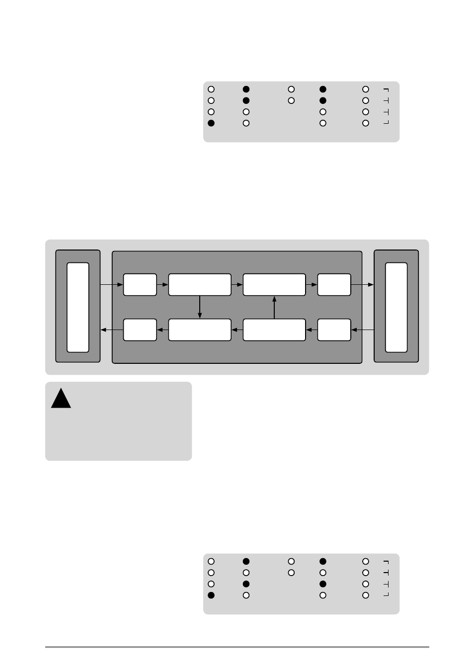
This setting allows to receive an AES3 signal and an AES3id simultaneously.
The AES3 input signal is converted to AES3id and the AES3id signal is con-
verted to the AES3. The clock rate of the incoming AES3 signal is extracted
and supplied as clock reference to the first SRC, which feeds the AES3 out-
put. The clock rate of the incoming AES3id signal is extracted and supplied
as clock reference to the second SRC, which feeds the AES3id output.
That means, the AES3 input is predefined as clock source for the first SRC,
the AES3 output. The AES3id input is predefined as clock source for the
second SRC, the AES3id output. There are no other adjustments for clock
sources possible within the X-SRC mode.
When the incoming digital audio signals can be locked as clock references,
the two blue LEDs »LOCK« in the »STATUS« menu will light constantly. The
clock rate of the clock sources are displayed in the »REF CLOCK
IN
« menu
under »1« and »2«. The identifier »1« generally indicates the sampling rate
of the first digital audio format selected in the »AUDIO
IN
« menu, seen
from above of the LED row. The identifier »2« generally indicates the samp-
ling rate of the second digital audio format, displayed below the first one.
Further Setting Examples
X-SRC
BI-DIR
UNI-DIR
AES3
S/P-DIF op
SRC
REFERENCE
88.2
48.0
44.1
32.0
192.0
96.0
176.4
MODE
AES3id
S/P-DIF co
AUDIO
IN
AES11
WCLK
AES3
S/P-DIF op
AES3id
S/P-DIF co
Input:
AES3id
44.1kHz
Output:
AES3id
44.1kHz
Output:
AES3
48.0kHz
Input:
AES3
48.0kHz
1. PLL:
Clock Extraction
44.1kHz
2. SRC:
Clock Conversion
44.1kHz ← 48.0kHz
2. PLL:
Clock Extraction
48.0kHz
1. SRC:
Clock Conversion
44.1kHz → 48.0kHz
Clock
44.1kHz
Clock
48.0kHz
MC-6: X-SRC Mode
Ef
fects Processor
44.1kHz
Digital Mixing Desk
48.0kHz
X-SRC Mode between AES3 and S/P-DIF optical.