3 voltage and current rms calculation, Voltage and current rms calculation, Figure 4. voltage and current rms calculations – Maxim Integrated 78M6631 User Manual
Page 9: 𝐼𝑅𝑀𝑆 = � ∑ in
UG_6631_078
78M6631 Firmware Description Document
Rev 2
9
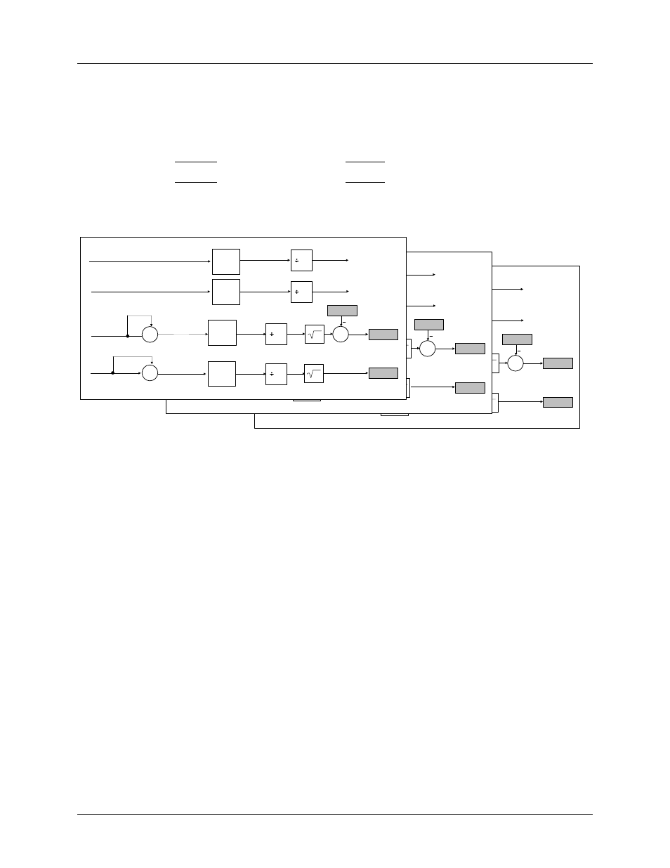
2.2.3 Voltage and Current RMS Calculation
As shown in Figure 4, the voltage and current channels ADC output samples are used to continually
compute the RMS (root mean square). The RMS is obtained by performing the square sum of the
instantaneous samples of voltage and current over a time interval (commonly referred as accumulation
time) and then performing a square root of the result:
𝑉𝑅𝑀𝑆 = �
∑
Vn
2
N−1
n=0
N
2
𝐼𝑅𝑀𝑆 = �
∑
In
2
N−1
n=0
N
2
In Figure 4, the output registers are represented in gray.
IC_SQ
VC_SQ
IC_SQSUM
VC_SQSUM
IC_RAW
IrmsC
VrmsC
IB_SUM
IB_OFFS
VC1
N
∑
N-
1
X
n=
0
∑
N-1
n=0
∑
N-1
n=0
PHASE C
IC1
VC_RAW
VB_SUM
VB_OFFS
∑
N-
1
n=
0
N
N
X
N
+
Iroff
IB_SQ
VB_SQ
IB_SQSUM
VB_SQSUM
IB_RAW
IrmsB
VrmsB
IB_SUM
IB_OFFS
VB1
N
∑
N-
1
X
n=
0
∑
N-1
n=0
∑
N-1
n=0
PHASE B
IB1
VA_RAW
VB_SUM
VB_OFFS
∑
N-
1
n=
0
N
N
X
N
+
Iroff
IA_SQ
VA_SQ
IA_SQSUM
VA_SQSUM
IA_RAW
Irms A
Vrms A
IA_SUM
IA_OFFS
VA1
N
X
PHASE A
IA1
VA_RAW
VA_SUM
VA_OFFS
N
N
X
N
+
Iroff
∑
N-1
n=0
∑
N-1
n=0
∑
N-1
n=0
∑
N-1
n=0
Figure 4. Voltage and Current RMS Calculations