3 serial peripheral interface (spi), Serial peripheral interface (spi), Table 2: spi command description – Maxim Integrated 78M6631 User Manual
Page 17: Section 3
UG_6631_078
78M6631 Firmware Description Document
Rev 2
17
3 Serial Peripheral Interface (SPI)
The 78M6631 has an on-chip SPI interface. The interface is slave (only) and can communicate directly on
the MPU data bus without FW overhead.
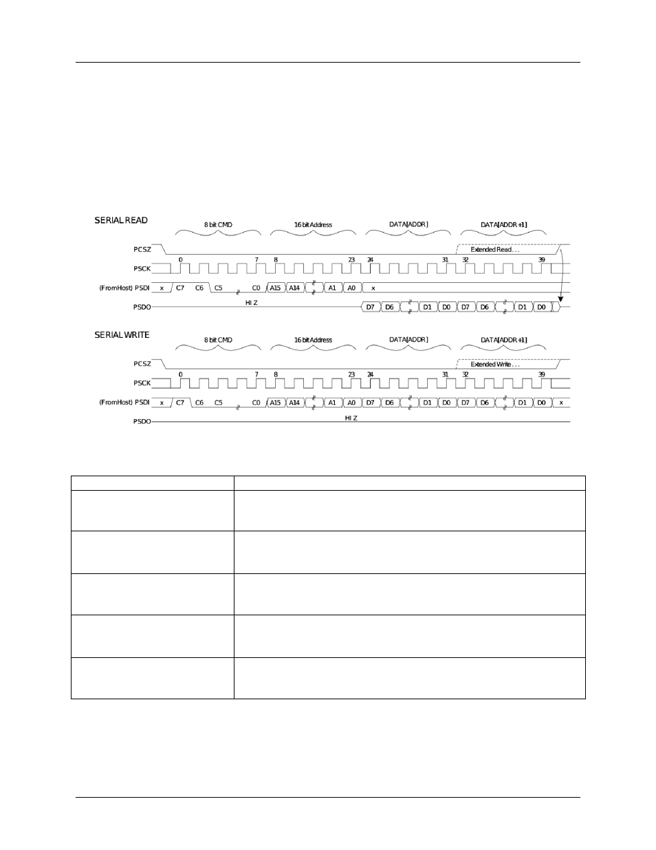
A typical SPI transaction is as follows: While PCSZ is high, the port is held in an initialized/reset state.
During this state, PSDO is held in high-Z state and all transitions on PCLK and PSDI are ignored. When
PCSZ falls, the port will begin the transaction on the first rising edge of PCLK. A transaction consists of
an 8-bit command, a 16-bit address, and then one or more bytes of data. The transaction ends when
PCSZ is raised. Some transactions may consist of a command only.
(From 78M6631)
(From 78M6631)
Table 2: SPI Command Description
Command
Description
11xx xxxx ADDR D0 ... DN
Output data on PSDO is read from RAM starting with byte at ADDR.
ADDR will auto-increment until PCSZ is raised.
MPU SPI interrupt is generated if xx xxxx is not equal to 0.
1100 0000 ADDR D0 ... DN
Output data on PSDO is read from RAM starting with byte at ADDR.
ADDR will auto-increment until PCSZ is raised.
No MPU SPI interrupt is generated because xx xxxx equals 0.
10xx xxxx ADDR D0 ... DN
Input data on PSDI is written to RAM starting with byte at ADDR.
ADDR will auto-increment until PCSZ is raised.
MPU SPI interrupt is generated if xx xxxx is not equal to 0.
1000 0000 ADDR D0 ... DN
Input data on PSDI is written to RAM starting with byte at ADDR.
ADDR will auto-increment until PCSZ is raised.
No MPU SPI interrupt is generated because xx xxxx equals 0.
CMD ADDR D0 ... DN
CMD and ADDR are available to the CPU in IORAM
D0 … DN are ignored.
MPU SPI interrupt is generated