4 active, reactive and apparent power calculation, Active, reactive and apparent power calculation, Va = i – Maxim Integrated 78M6631 User Manual
Page 10
78M6631 Firmware Description Document
UG_6631_078
10
Rev 2
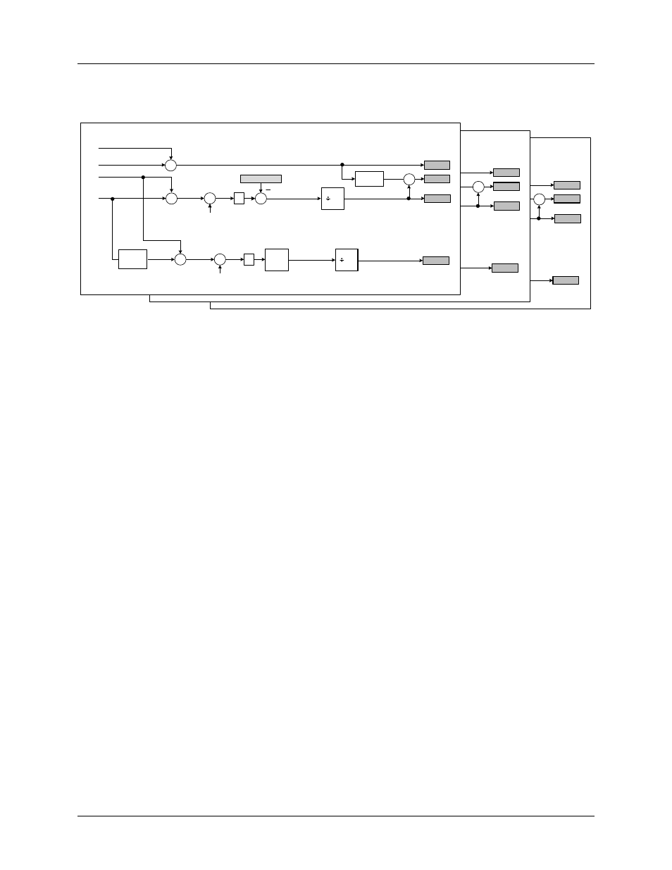
2.2.4 Active, Reactive and Apparent Power Calculation
Figure 5 shows the signal processing chain for active and reactive power calculations.
IC1
VC1
WATTSUM_C
Quadrature
Delay
X
LPF
Σ
(TMP)
LPF
Σ
+
X
WATT C
VAR C
Poff
X
VA C
INVERSE
X
PF C
VqC
N
N
∑
N-1
n=0
VrmsC
IrmsC
(TMP)
PHASE C
IB1
VB1
WATTSUM_B
Quadrature
Delay
X
LPF
Σ
(TMP)
LPF
Σ
+
X
WATT B
VAR B
Poff
X
VA B
INVERSE
X
PF B
VqB
N
N
∑
N-1
n=0
VrmsB
IrmsB
(TMP)
PHASE B
IA1
VA1
WATTSUM_A
Quadrature
Delay
X
LPF
Σ
(TMP)
LPF
Σ
+
X
WATT A
VAR A
Poff
X
VA A
INVERSE
X
PF A
VqA
N
N
∑
N-1
n=0
VrmsA
IrmsA
(TMP)
PHASE A
Figure 5. Power and Power Factor Signal Processing Chain
Active Power
The instantaneous power is obtained multiplying instantaneous voltage and current samples. The product
is then averaged over N conversions (accumulation time) to compute active power (WATTA, WATTB and
WATTC), the aggregate value (WATTS) is the sum of the 3 phases active power average.
Apparent Power
The apparent power (VA-A, VA-B, VA-C) is the product of rms voltage (VrmsA, VrmsB, and VrmsC) and
rms current (IrmsA, IrmsB, IrmsC):
VA = I
RMS
x V
RMS
Reactive Power
The reactive power is calculated as multiplication of instantaneous samples of current (IA1, IB1, IC1) and
the instantaneous quadrature voltage (VqA, VqB, VqC). The quadrature voltage is obtained through a 90°
phase shift (quadrature delay) of the voltage samples. The samples are then averaged over the
accumulation time interval and updated in the VARA, VARB, and VARC registers.