4 graphical user interfaces, 1 gui for maxrefdes24, 1 usb2pmb adapter – Maxim Integrated MAXREFDES24EVSYS User Manual
Page 9: Graphical user interfaces, Gui for maxrefdes24, Usb2pmb adapter
MAXREFDES24EVSYS User Manual
Rev 0
9
4 Graphical User Interfaces
Before launching the GUI applications, make sure the USB2PMB1 and MAXADCLITE2 boards are connected
to the PC as described in the previous section.
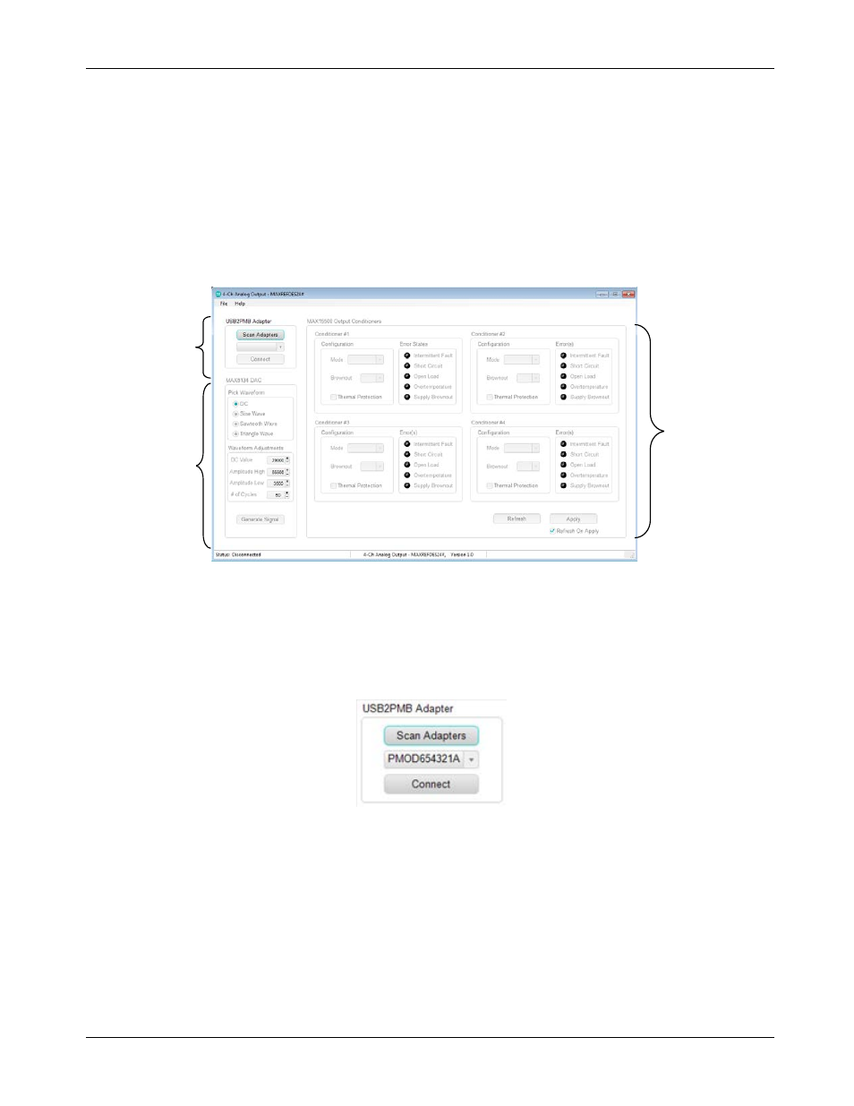
4.1 GUI for MAXREFDES24
With the USB2PMB1 board connected, run (double-click) the 4-Ch_Analog_Output.exe file located in the
\MAXREFDES24\ directory of the USB flash drive. Once the GUI window appears, only the USB connectivity
section will be active. The other two sections for the analog signal chain components are grayed out until the
USB connection is established
4.1.1 USB2PMB Adapter
USB connectivity is managed in the USB Adapter section located in the upper left-hand corner of the
application. Click Scan Adapters to discover any compatible USB2PMB devices (starting with PMOD). If no
adapters are found, the GUI offers the user the ability to enter into a “Demo GUI” mode where the user can
exercise the features of the GUI without communicating to any hardware. Click on Connect once the adapter
starting with PMODxxxxxxx appears.
USB
CONNECTIVITY
MAX15500
OUTPUT
CONDITIONER
CONFIGURATION
AND STATUS
MAX5134
DAC CODE
GENERATION