3 hardware connections, 1 usb2pmb1 to maxrefdes24, 2 24vdc to maxrefdes24 – Maxim Integrated MAXREFDES24EVSYS User Manual
Page 6: Hardware connections, Usb2pmb1 to maxrefdes24, 24vdc to maxrefdes24
MAXREFDES24EVSYS User Manual
Rev 0
6
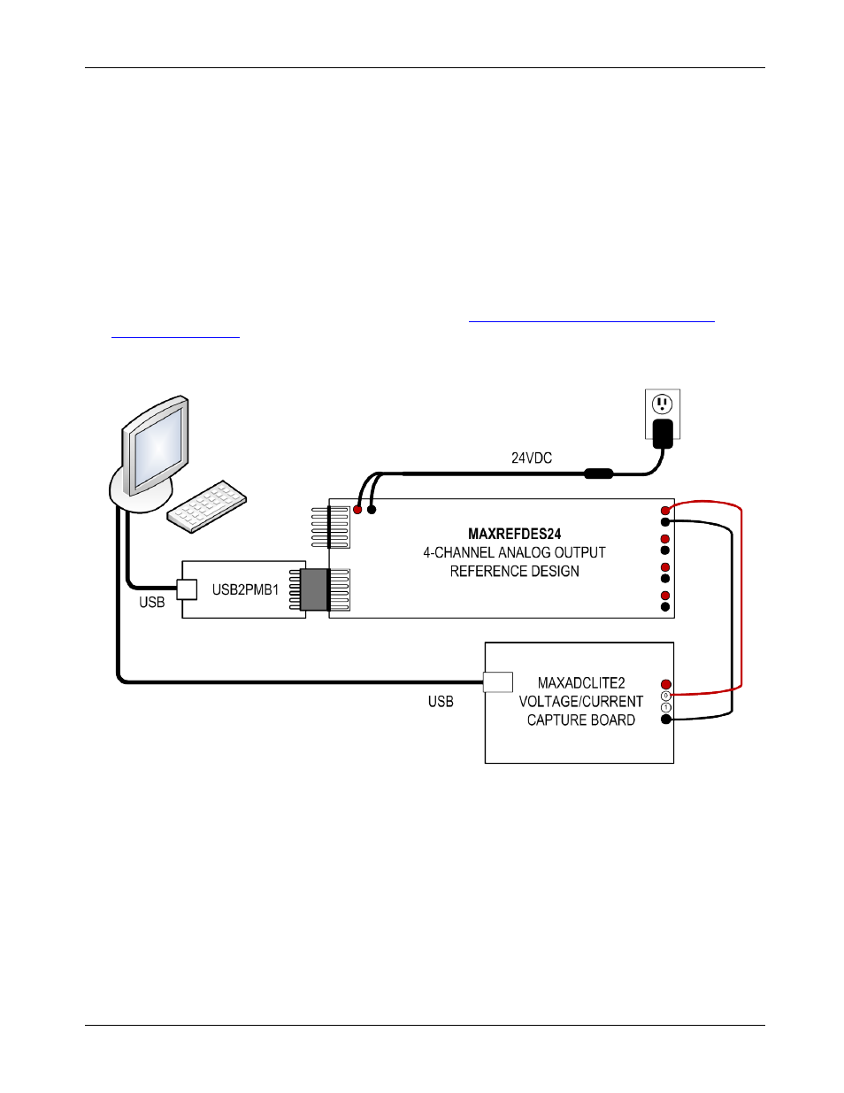
3 Hardware Connections
This section describes the basic connections with the MAXREFDES24EVSYS kit.
• The user must provide a Windows PC with two available USB ports and an AC outlet for operating the
MAXREFDES24EVSYS kit. In addition to providing PC communications, the USB ports power the
USB2PMB1 and MAXADCLITE2 boards.
• A universal AC wall adapter and test clip adapter are included for providing 24V DC to the MAXREFDES24
analog output board. Any DC supply with 20–30V DC and >150mA output capabilities can be substituted
for the AC wall adapter.
• The MAXREFDES24 and USB2PMB1 boards mate together via a 12-pin Pmod Type 2A connector. For
more information on the Pmod form factor, refer to t
or visit
• A pair of wires with test clips is provided for establishing an analog control signal between one of the
MAXREFDES24 outputs and one of the MAXADCLITE2 inputs.
3.1 USB2PMB1 to MAXREFDES24
Connect the MAXREFDES24 board to the USB2PMB1 adapter as shown above. Both 12-pin connectors
should be on the same side of the PCB when mated together.
3.2 24VDC to MAXREFDES24
Connect the color coded test clips of the DC power adapter to the MAXREFDES24 board as shown above.
Red clips connect to +24V and black clips connect to PGND.