4 schematics, bill of materials, and pcb layouts, 1 78m6610+psu 16-pin evaluation board schematics, Schematics, bill of materials, and pcb layouts – Maxim Integrated 78M6610+PSU Evaluation Kit User Manual
Page 14: 78m6610+psu 16-pin evaluation board schematics
78M6610+PSU Evaluation Kit User Manual
14
Rev 2
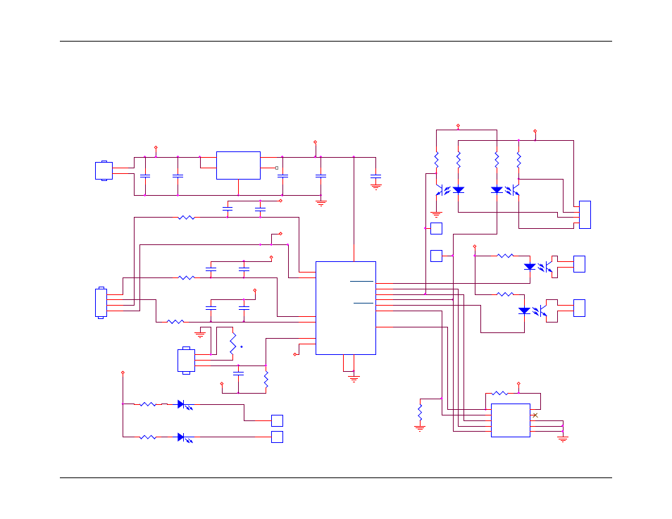
4 Schematics, Bill of Materials, and PCB Layouts
This section includes the schematics, bill of materials, and PCB layouts for the 78M6610+PSU Evaluation Boards and the Shunt Adaptor Board.
4.1
78M6610+PSU 16-Pin Evaluation Board Schematics
Figure 5: 78M6610+PSU 16-Pin Evaluation Board Electrical Schematic
t
RT1
DNP THERMISTOR
TP12
DNP TP
1
J5
Vin Ext
1
2
3
3.3V
ISO UART TX
C14
0.1UF
0603
/AC_CRITICAL
C5
0.1UF
0603
R5
3k
0603
C13
1000pF
0603
/RELAY CTRL
D1
GREEN or BLUE
C7
1000pF
0603
J13
CON2
1
2
R21 220
0603
R15
360
0603
TP14
DNP TP
1
UART TX
3.3V
3.3V
U1
MC78PC33
SOT23-5
GN
D
2
EN
3
VOUT
5
VIN
1
NC
4
3.3V
3.3V
3.3V
J2
5V
1
2
3.3V
C2
0.1uF
0603
5V
C1
4.7uF
0805
C4
0.1uF
0603
C3
4.7uF
0805
J3
UART
1
2
3
4
UA
RT
RX
TP15
DNP TP
1
COMM 5V RETURN
R18
500
0603
COMM 5V
R16
500
0603
.
J7
SPI PORT
DIO8
1
SSB
2
MOSI
3
SCK
4
MISO
5
GND
6
GND
7
*RESET
9
V3P3
10
GND
8
R25
750
0603
U4
TCMT1107
1
2
4
3
D2
RED
R23 220
0603
U5
TCMT1107
1
2
4
3
3.3V
R17
150
0603
R4
39
0603
C17
0.1uF
0603
LOAD RETURN
NEUTRAL
LINE_SENSE
NEUTRAL
3.3V
COMM 5V
Connection for external
10K NTC Thermistor
J4
4 HEADER
1
2
3
4
R8
750
0603
C15
1000pF
0603
C16
0.1uF
0603
3.3V
U6
TCMT1107
1
2
4
3
/RELAY CTRL
U9
TCMT1107
1
2
4
3
J16
CON2
1
2
R22 500
0603
ISO UART RX
R13
500
0603
3.3V
R14
10K
0603
/AC_CRITICAL
C6
0.1uF
0603
TP11
DNP TP
1
U3
78M6610+PSU/C
V3P3A
13
AIP
14
G
NDA
3
AIN
15
AVP
1
ATEMP1
16
SSB/DIR
6
SPCK/ADDR0
12
ACCRIT
7
SDI/RX/SDAO
11
AVN
2
ACFAULT
5
IFCONFIG
4
G
NDD
9
SDO/TX/SDAI
10
V
3P
3
D
8
R7
750
0603
DNP
DNP
DNP