4 jumper and switch settings, Jumper and switch settings – Maxim Integrated 78M6610+PSU Evaluation Kit User Manual
Page 11
78M6610+PSU Evaluation Kit User Manual
Rev 2
11
2.4
Jumper and Switch Settings
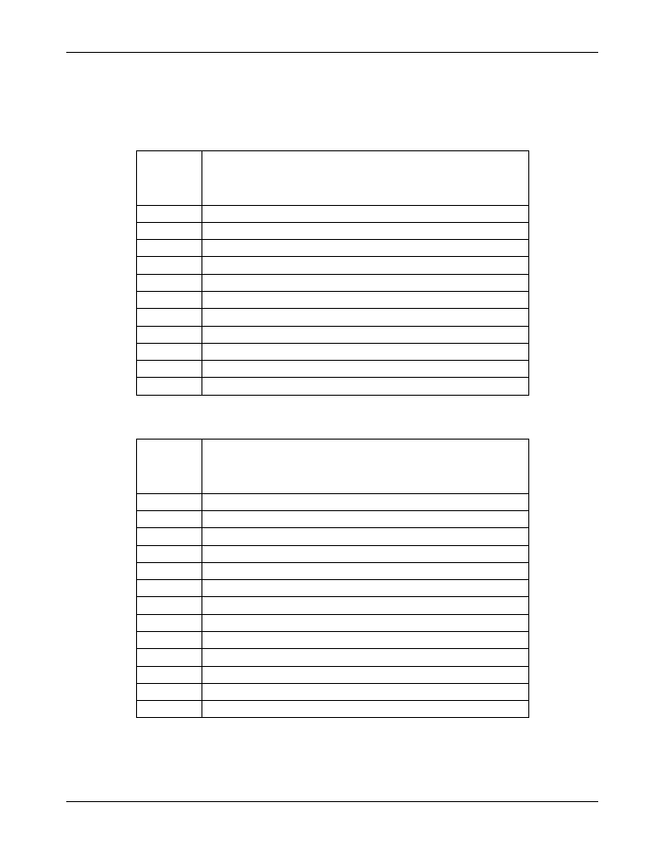
The following tables describe the 78M6610+PSU Evaluation Kit jumpers and switches and their setting for
different configurations.
Table 1: 16-Pin Evaluation Board Connector Descriptions
Schematic
and
Silkscreen
Reference
Description
J2
Power Connector to Shunt Adaptor Board
J3
Sensor Connector to Shunt Adaptor Board
J4
UART Connector to Shunt Adaptor Board
J5
External Temperature Sensor Connector
J7
SPI Connector
J13
Relay Connector
J14
AC Critical Connector
TP11
Optional Relay LED Connector
TP12
Optional AC Critical LED Connector
TP14
UART RX Test Point
TP15
UART TX Test Point
Table 2: 24-Pin Evaluation Board Connector Descriptions
Schematic
and
Silkscreen
Reference
Description
J2
Power Connector to Shunt Adaptor Board
J3
Sensor Connector to Shunt Adaptor Board
J4
UART Connector to Shunt Adaptor Board
J5
External Temperature Sensor Connector
J7
SPI Connector
J13
Relay Connector
J14
AC Critical Connector
J16
AC Fault Connector
TP11
Optional Relay LED Connector
TP12
Optional AC Critical LED Connector
TP13
Optional AC Fault LED Connector
TP14
UART RX Test Point
TP15
UART TX Test Point