2 design 5 pxl-100 connections, Ms-3000 microstar reader, Quick s tart guide ms-3000 – Keri Systems MS-3000 User Manual
Page 4
MS-3000 MicroStar Reader
2305 Bering Drive
01815-001 Rev. H
San Jose, CA 95131 USA
(800) 260-5265 (408) 435-8400 FAX (408) 577-1792
Web: www.kerisys.com E-mail: [email protected]
Page 4 of 8
Quick S
tart Guide
MS-3000
3.2
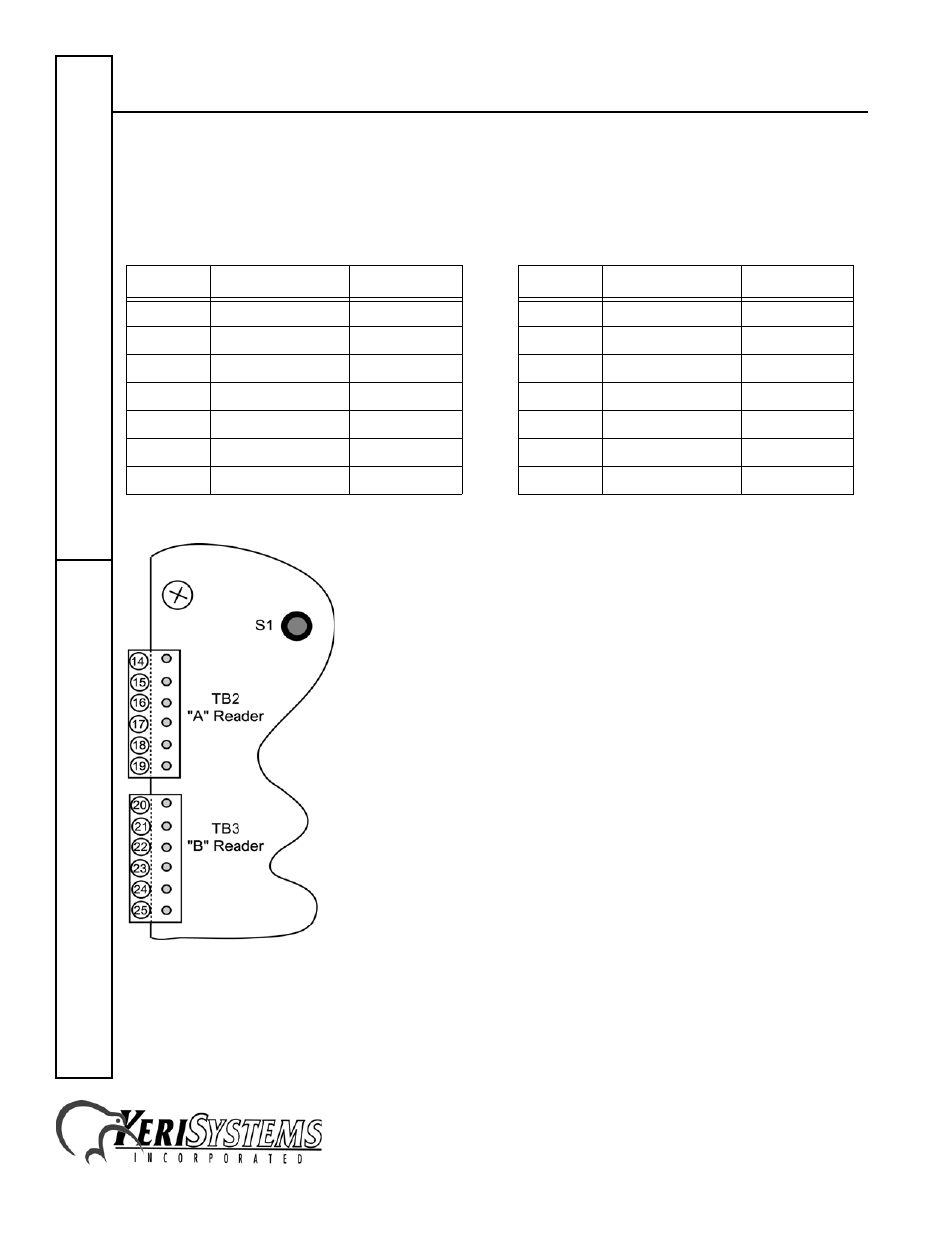
Design 5 PXL-100 Connections
The "A" reader connects to TB2, pins 14 through 19. The "B" reader to TB3, pins 20 through 25.
Connecting the PXL-100 – TB2
Connecting to the PXL-100 – TB3
Figure 3: Design 5 PXL-100 Connections
NOTE: Please contact customer support at Keri Systems for information regarding connecting a
Reader to a Design 4 PXL-100. A Design 4 PXL-100 can be identified by the location of its power
connection made at the middle of the left edge of the printed circuit board.
Pin #
Function
Wire Color
Pin #
Function
Wire Color
14
Green LED
Brown
20
Green LED
Brown
15
Beeper
Green
21
Beeper
Green
16
Reader Power
Red
22
Reader Power
Red
17
Reader Ground
Black
23
Reader Ground
Black
17
Shield
Silver
23
Shield
Silver
18
Reader Antenna
Blue
24
Reader Antenna
Blue
19
Red LED
White
25
Red LED
White