Carrier 48TC**16 User Manual
Page 8
8
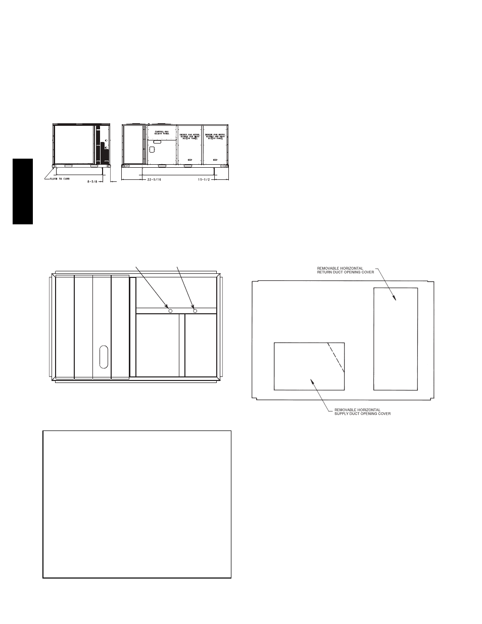
Positioning on Curb —
For full perimeter curbs CRRFCURB074A00 and 075A00,
the clearance between the roof curb and the front and rear
base rails should be
1
/
4
in (6.4 mm). The clearance between
the curb and the end base rails should be
1
/
2
in (13 mm). For
retrofit applications with curbs CRRFCURB003A01 and
4A01, the unit should be position as shown in Fig. 6.
Maintain the 15.5 in (394 mm) and 8
5
/
8
in (220 mm)
clearances and allow the 22
5
/
16
in (567 mm) dimension to
float if necessary.
C10003
Fig. 6 -- Retrofit Installation Dimensions
If the alternative condensate drain location through the
bottom of the unit is used in conjunction with a retrofit
curb, the hole in the curb must be moved 12.5 in (320
mm) towards the duct end of the unit. (See Fig. 7.)
Original
Position
New Position
(moved 12.5 in.)
C10904
Fig. 7 -- Alternative Condensate Drain Hole Positions
Although unit is weatherproof, guard against water from
higher level runoff and overhangs.
IMPORTANT:
If the unit has the factory--installed Thru--the--Base
option, make sure to complete installation of the option
before placing the unit on the roof curb.
See the following sections:
S
Factory--Option Thru--Base Connections
(Gas Connection) on page 11
S
Factory--Option Thru--Base Connections
(Electrical Connections) on page 17
NOTE: If gas and/or electrical connections are not
going to occur at this time, tape or otherwise cover the
fittings so that moisture does not get into the building or
conduit in the interim.
Remove all shipping materials and top skid. Remove extra
center post from the condenser end of the unit so that the
condenser end of the unit matches Figs. 26 and 27.
Recycle or dispose of all shipping materials.
Step 7 — Convert to Horizontal and Connect
Ductwork (when required)
Unit is shipped in the vertical duct configuration. Unit
without factory--installed economizer or return air smoke
detector option may be field--converted to horizontal ducted
configuration using accessory CRDUCTCV001A00. To
convert to horizontal configuration, remove screws from side
duct opening covers and remove covers.
Discard the supply duct cover. Install accessory
CRDUCTCV001A00 to cover the vertical supply duct
opening. Use the return duct cover removed from the end
panel to cover the vertical return duct opening.
Field--supplied flanges should be attached to horizontal
duct openings and all ductwork should be secured to the
flanges. Insulate and weatherproof all external ductwork,
joints, and roof or building openings with counter flashing
and mastic in accordance with applicable codes.
Do not cover or obscure visibility to the unit’s informative
data plate when insulating horizontal ductwork.
C06108
Fig. 8 -- Horizontal Conversion Panels
48TC
**16