Carrier 48TC**16 User Manual
Page 5
5
Roof Mount —
Check
building
codes
for
weight
distribution
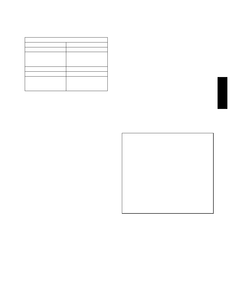
requirements. Unit operating weight is shown in Table 1.
Table 1 – Operating Weights
48TC**16
COMPONENT
UNITS LB (KG)
Base Unit
1380 (627)
Economizer
Vertical
100 (45)
Horizontal
115 (52)
Humidi---MiZer
R
System
62 (28)
Powered Outlet
32 (15)
Curb
14---in/356 mm
180 (82)
24---in/610 mm
235 (107)
Step 2 — Plan for Sequence of Unit Installation
The support method used for this unit will dictate different
sequences for the steps of unit installation. For example,
on curb--mounted units, some accessories must be
installed on the unit before the unit is placed on the curb.
Review the following for recommended sequences for
installation steps.
Curb--mounted installation —
Install curb, making sure to position the common cross
rail (see Fig. 3) for large duct opening.
Install field--fabricated ductwork inside curb
Complete installation of the factory--installed
thru--the--base service connection option
Prepare bottom condensate drain connection to suit
planned condensate line routing (refer to Step 9 for
details)
Rig and place unit
Install outdoor air hood
Install condensate line trap and piping
Make electrical connections
Install other accessories
Pad--mounted installation —
Prepare pad and unit supports
Check and tighten the bottom condensate drain
connection plug
Rig and place unit
Convert unit to side duct connection arrangement
Install field--fabricated ductwork at unit duct openings
Install outdoor air hood
Install condensate line trap and piping
Make electrical connections
Install other accessories
Frame--mounted installation —
Frame--mounted applications generally follow the
sequence for a curb installation. Adapt as required to
suit specific installation plan.
Step 3 — Inspect Unit
Inspect unit for transportation damage. File any claim
with transportation agency.
Confirm before installation of unit that voltage, amperage
and circuit protection requirements listed on unit data
plate agree with power supply provided.
Step 4 — Provide Unit Support
Roof Curb Mount —
Accessory roof curb details and dimensions are shown in
Fig. 3. Assemble and install accessory roof curb in
accordance with instructions shipped with the curb.
NOTE: The gasketing of the unit to the roof curb is
critical for a watertight seal. Install gasket supplied with
the roof curb as shown in Fig. 3. Improperly applied
gasket can also result in air leaks and poor unit
performance.
Curb should be level. This is necessary for unit drain to
function properly. Unit leveling tolerances are show in
Fig. 4. Refer to Accessory Roof Curb Installation
Instructions for additional information as required.
Install insulation, cant strips, roofing felt, and counter
flashing as shown. Ductwork must be attached to curb and
not to the unit.
IMPORTANT:
If the unit’s gas connection and/or electric and control
wiring is to be routed through the basepan and the unit
is equipped with the factory--installed Thru--the--Base
service option see the following sections:
S
Factory--Option Thru--Base Connections
(Gas Connection) on page 11
S
Factory--Option Thru--Base Connections
(Electrical Connections) on page 17
If using the field--installed Thru--the--Base accessory
follow the instructions provided with the accessory kit.
NOTE: If gas and/or electrical connections are not
going to occur at this time, tape or otherwise cover the
fittings so that moisture does not get into the building or
conduit in the interim.
Slab Mount (Horizontal Units Only) —
Provide a level concrete slab that extends a minimum of
6 in. (150 mm) beyond unit cabinet. Install a gravel apron
in front of condenser coil air inlet to prevent grass and
foliage from obstructing airflow.
NOTE: Horizontal units may be installed on a roof curb
if required.
Alternate Unit Support
(In Lieu of Curb or Slab Mount) —
A non--combustible sleeper rail can be used in the unit curb
support area. If sleeper rails cannot be used, support the long
sides of the unit with a minimum of 3 equally spaced 4--in. x
4--in. (102 mm x 102 mm) pads on each side.
48TC
**16