Carrier 48TC**16 User Manual
Page 18
18
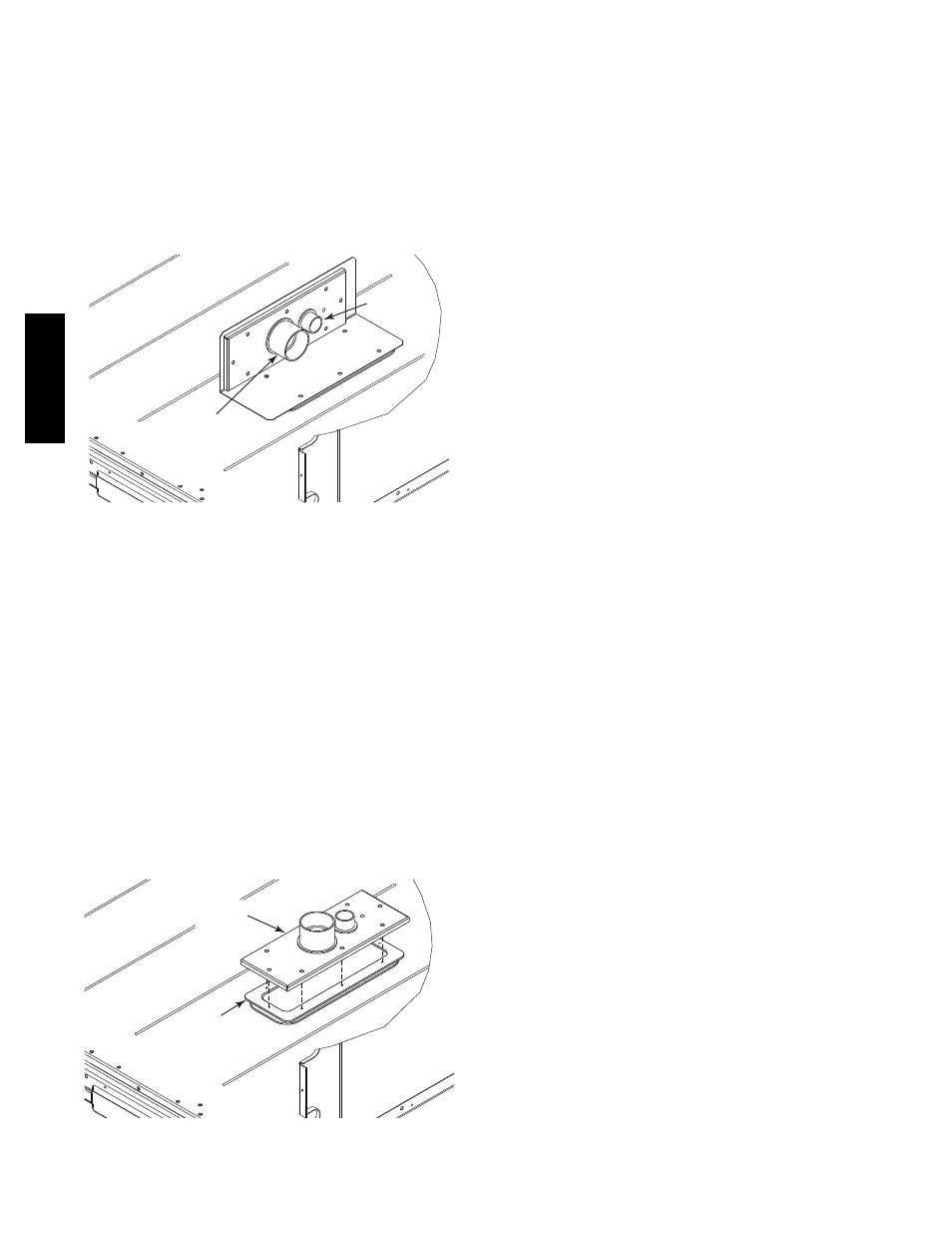
Factory--Option Thru--Base Connections
(Electrical Connections)—
This service connection kit consists of a
1
/
2
--in electrical
bulkhead connector and a 1
1
/
2
--in electrical bulkhead
connector, connected to an “L” bracket covering the
embossed (raised) section of the unit basepan in the
condenser section. See Fig. 36. The
1
/
2
--in bulkhead
connector enables the low--voltage control wires to pass
through the basepan. The 1
1
/
2
--in electrical bulkhead
connector allows the high--voltage power wires to pass
through the basepan.
1
/
2
” ELECTRICAL
BULKHEAD
CONNECTOR
1
1
/
2
” ELECTRICAL
BULKHEAD
CONNECTOR
C10907
Fig. 36 -- Thru--the--Base Option, Shipping Position
1. Remove the “L” bracket assembly from the unit.
2. Remove connector plate assembly from the “L”
bracket and discard the “L” bracket, but retain the
washer head screws and the gasket (located between
the “L” bracket and the connector plate assembly).
NOTE: Take care not to damage the gasket, as it is
reused in the following step.
3. Place the gasket over the embossed area in the
basepan, aligning the holes in the gasket to the holes
in the basepan. See Fig. 37.
4. Install the connector plate assembly to the basepan
using 8 of the washer head screws.
NOTE: If electrical connections are not going to occur at
this time, tape or otherwise cover the fittings so that
moisture does not get into the building or conduit in the
interim.
GASKET
CONNECTOR
PLATE
ASSEMBLY
C10908
Fig. 37 -- Completing Installation of Thru--the--Base
Option
Check tightness of connector lock nuts before connecting
electrical conduits.
Field--supplied and field--installed liquid tight conduit
connectors and conduit may be attached to the connectors
on the basepan. Pull correctly rated high voltage and low
voltage through appropriate conduits. Connect the power
conduit to the internal disconnect (if unit is so equipped)
or to the external disconnect (through unit side panel). A
hole must be field cut in the main control box bottom on
the left side so the 24--v control connections can be made.
Connect the control power conduit to the unit control box
at this hole.
Units without Thru--Base Connections —
1. Install power wiring conduit through side panel open-
ings. Install conduit between disconnect and control
box.
2. Install power lines to terminal connections as shown
in Fig. 31.
Field Control Wiring —
The 48TC**16 requires an external temperature control
device. This device can be a thermostat (field--supplied)
or a PremierLink controller (available as factory--installed
option or as field--installed accessory, for use on a Carrier
Comfort Network or as a stand alone control) or the RTU
Open Controller for Building Management Systems using
non--CCN protocols (RTU Open is available as a
factory--installed option only).
Thermostat —
Install
a
Carrier--approved
accessory
2
stage
Cooling/Heating thermostat according to installation
instructions included with the accessory. If using an
electronic thermostat, configure it for “non--heat pump”
operation. Locate the thermostat accessory on a solid wall
in the conditioned space to sense average temperature in
accordance with the thermostat installation instructions.
If the thermostat contains a logic circuit requiring 24--v
power, use a thermostat cable or equivalent single leads of
different colors with minimum of seven leads. If the
thermostat does not require a 24--v source (no “C”
connection required), use a thermostat cable or equivalent
with minimum of six leads. Check the thermostat
installation instructions for additional features which
might require additional conductors in the cable.
For wire runs up to 50 ft. (15 m), use no. 18 AWG
(American Wire Gage) insulated wire (35_C minimum).
For 50 to 75 ft. (15 to 23 m), use no. 16 AWG insulated
wire (35_C minimum). For over 75 ft. (23 m), use no. 14
AWG insulated wire (35_C minimum). All wire sizes
larger than no. 18 AWG cannot be directly connected to
the thermostat and will require a junction box and splice
at the thermostat.
48TC
**16