Carrier 48TC**16 User Manual
Page 22
22
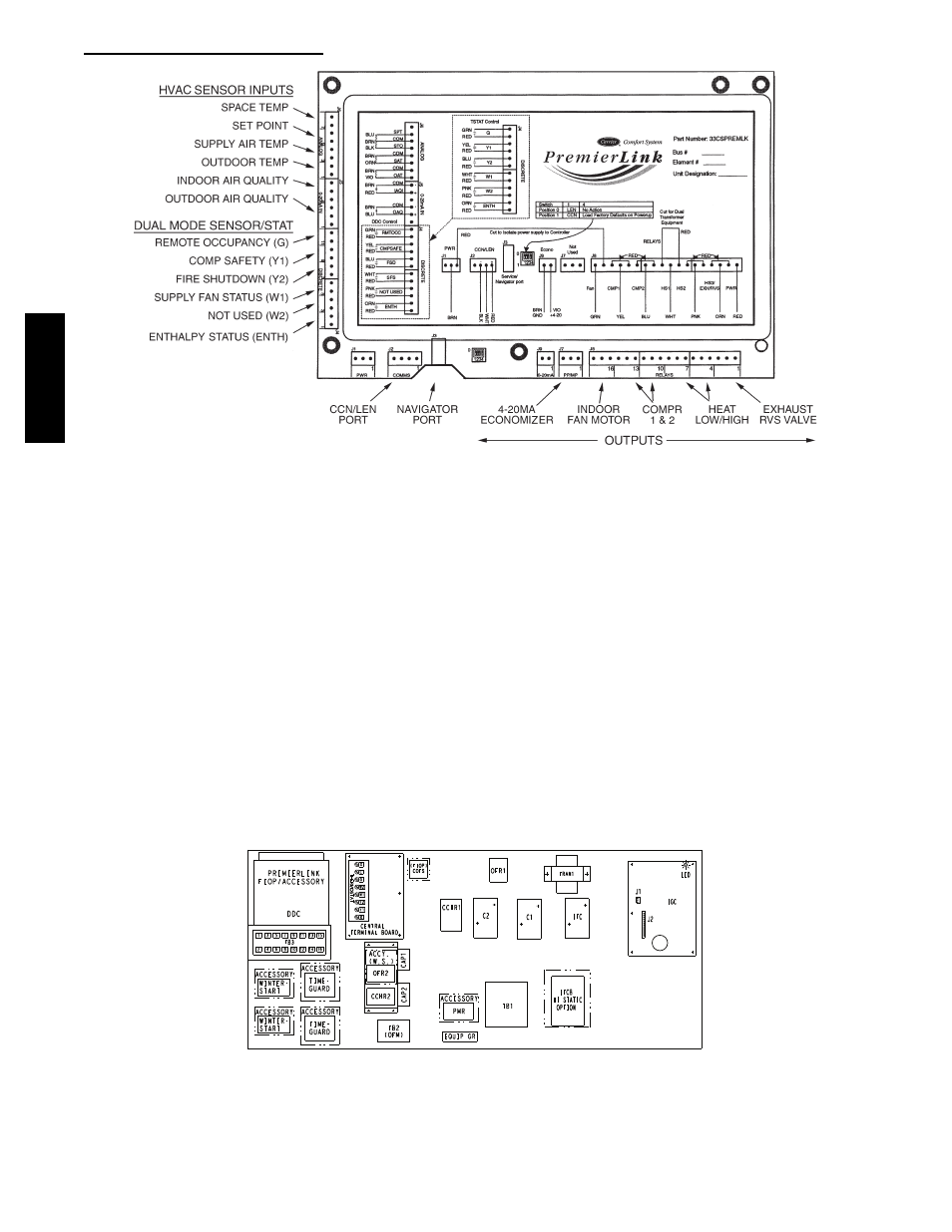
PremierLinkt (Factory Option)
C08199
Fig. 44 -- PremierLink Controller
NOTE:
Refer to Form 33CS--67SI for complete
PremierLink configuration, operating sequences and
troubleshooting information. Have a copy of this manual
available at unit start--up.
The PremierLink controller (see Fig. 44) is compatible
with Carrier Comfort Networkr (CCN) devices. This
control is designed to allow users the access and ability to
change factory--defined settings, thus expanding the
function of the standard unit control board. CCN service
access tools include System Pilot (TM), Touch Pilot (TM)
and Service Tool. (Standard tier display tools Navigatort
and Scrolling Marquee are not suitable for use with latest
PremierLink controller (Version 2.x).)
The PremierLink control is factory--mounted in the
48TC**16 unit’s main control box to the left of the
Central Terminal Board (CTB) (see Fig. 45). Factory
wiring is completed through harnesses connected to the
CTB. Field connections are made at a 16--pole terminal
block (TB3) located on the bottom shelf of the unit
control box in front of the PremierLink controller. The
factory--installed PremierLink control includes the
supply--air temperature (SAT) sensor. The outdoor air
temperature
(OAT)
sensor
is
included
in
the
FIOP/accessory EconoMi$ert2 package. (See page 34 for
accessory enthalpy controls.)
The PremierLink controller requires the use of a Carrier
electronic thermostat or a CCN connection for time
broadcast to initiate its internal timeclock. This is
necessary for broadcast of time of day functions
(occupied/unoccupied).
NOTE: PremierLink controller is shipped in Sensor mode.
To be used with a thermostat, the PremierLink controller
must be configured to Thermostat mode. Refer to
PremierLink Configuration instructions for Operating Mode.
C11189
Fig. 45 -- 48HC**14 Control Box Component Locations -- PremierLink Controller Location
48TC
**16