Installation, In an audio rack, Stacked – Philips CDC771V User Manual
Page 5: Video out, Ntsc/pal, 4 mains fuse holder (not all versions)
Attention! The text in this document has been recognized automatically. To view the original document, you can use the "Original mode".
INSTALLATION
x:
.2
ro
c
U1
POWER SUPPLY SETTING
CONNECTIONS
•
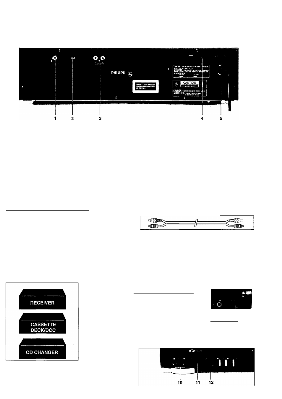
Check that the type plate on the rear of your changer
indicates the correct supply voltage.
•
If your mains supply voltage is different, consult your
dealer or our Service Organisation.
Certain versions of this changer are equipped with a voltage
selector 5, which enables you to set the player to the correct
mains voltage yourself. When changing the voltage setting, it
is also necessary to change the mains fuse 4 to one of the
correct rating: T250 mA (slow blow fuse) for 110/120 V,
T125mA (slow blow fuse) for 220/240V.
SITTING THE COMPACT DISC CHANGER_______________
Free standing
•
Always position the changer horizontally on a flat, firm
surface.
•
Allow a free space of at least 3 cm above the changer so
as not to interfere with the cooling of the changer.
In an audio rack
•
The changer can be sited in any desired position.
Stacked
•
Site the changer preferably at the bottom or at the top.
•
Never position the changer directly on top of a high-power
amplifier, as such an amplifier gives off a substantial
amount of heat.
VIDEO OUT
For connecting to the Video terminal of the TV, VCR, or AV
amplifier.
Wever connect this jack to the Audio input/output or
Digital input/output.
NTSC/PAL
Set the color TV system switch to the proper position,
NTSC or PAL, according to your TV. Make sure only to
change the setting when the changer is in the power off.
ANALOG OUT
For the connecting to the TV or amplifier.
•
Insert a red plug into the ‘R’ socket and the other plug into
the ‘L’ socket.
•
Insert the two other plugs into the corresponding sockets
of the CD or AUX input of your amplifier.
You can also use the TUNER or TAPE IN connection, but
never the PHONO input!
4 Mains fuse holder (not all versions)
See 'POWER SUPPLY SETTING’.
5 Voltage selector (not all versions)
See ‘POWER SUPPLY SETTING’.
CONNECTING HEADPHONES
•
Connect headphones with a 6.3
mm plug to the PHONES socket 17.
•
The sound level is adjusted with
the LEVEL control 18.
CONNECTING MICROPHONES
I
17
18
Connect the microphone(s) with a 6.3 min plug to the MIC
jack
10
.
The microphone level is adjusted with the MIC LEVEL 11.
The strength of echo is adjusted with the DIGITAL ECH012.