Philips CDI 615 User Manual
Page 23
Attention! The text in this document has been recognized automatically. To view the original document, you can use the "Original mode".
S P E C I F I C A T I O N S
For more Information refer to the supplied Technical Documentation
System
CD-Interactive
Usable discs
CD-I
CD-DA
PHOTO-CD
CD-i READY
CD BRIDGE
CD+GRAPHICS
VIDEO CD
CD DIGITAL
RS232 Serial Port #1, #2 (rear)
2 connectors DB9 male
Signals according EIA RS232 - E standard and CCiTTV.28
Baudrates up to 115200 baud are supported .
Power requirement
120VAC
50/60HZ
Power consumption
23W approx
Operating temperature
4rF(5"C)to95’F(35°C)
Relative humidity
5% to 95% (no condensation)
Weight
4,200 kg approx
Dimensions (w x h x d)
435 mm x 105 mm x 280 mm
17 1/8x4 1/8x11”
Connections
AT-keyboard Din connector (rear)
pin
signal
1
2
3
4
5
levels
clock
data
n.c.
GND
+5V (300 mA max)
TTL
pin
signal
I/O
1
DCD
1
2
RXD
1
3
TXD
0
4
DTR
0
5
GND
.
6
DSR
1
7
RTS
0
8
CTS
1
9
RI
1
levels
RS standard
Centronics parallel port #3 (rear)
25 pin sub D connector female
standard centronics interface / ECP / EPP for printers
and general purpose parallel I/O.
pin
signal
I/O
pin
signal
I/O
1
STROBE*
0
14
AOTOFDXT*
0
2
DO
I/O
15
ERROR*
1
3
D1
I/O
16
INIT* (reset)
0
4
D2
I/O
17
SEL* (select in)0
5
D3
I/O
18
GROUND
-
6
D4
I/O
19
GROUND
-
7
D5
I/O
20
GROUND
-
8
D6
I/O
21
GROUND
-
9
D7
I/O
22
GROUND
-
10
ACK*
1
23
GROUND
-
11
BUSY
1
24
GROUND
-
12
PE (paper empty) 1
25
GROUND
-
13
SEL (on-line)
1
’ Low = active
Levels TTL
Digital out (rear)
0,5 Vpp Into 75 ohm
RCA pin cinch socket
Pointing device input 1 and input 2 (front)
(2 ports) 8-pin mlnl-DIN
Y/C (S-vIdeo) (rear)
minl-DINI 4-pin
pin
signal
GND
GND
Y (IVpp into 75 ohm)
C (burst 300mVpp into 75 ohm)
RFI/0
Connector
F-type
Antenna input 75 ohm unbal
out to TV
75 ohm unbal with
*CD-i RF out to TV = 66 dBrv
* antenna RF out to TV = loop through (CD-i power off)
Channel selector
ch3=61.250
MHz
Ch4=67.250
MHz
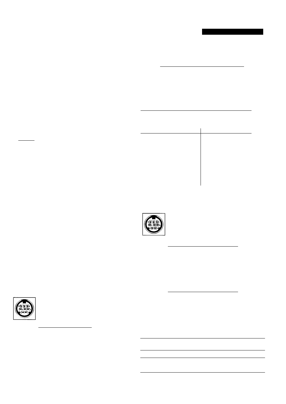
serial I/O (rear) (1 ports) 8-pin mini-DIN
pin
signal
1
nc
2
rxd
3
txd
4
nc
5
ground
6
cts
7
rts
8
+5V (100 mA max)
I/O
mini-DIN input 1
pin
signal
I/O
1
n.c.
.
2
rxd2
1
3
txd2
-
4
n.c.
-
5
gnd
-
6
n.c.
-
7
rts2
0
8
+5V (100 mA max)
0
levels
TTL
mini-DIN input 2
pin
signal
I/o
1
n.c.
.
2
rxdl
1
3
n.c.
0
4
n.c.
-
5
gnd
-
6
n.c.
-
7
rtsi
0
8
+5V (100 mA max)
0
levels
TTL
Pointing device speed of 1200 baud is supported.
I
O
I
O
Serial communication at 9600 baud.
Audio out
2 Vrms
2 channel individual RCA pin cinch sockets
video out (NTSC)1 Vpp (75 Ohm load, sync neg) RCA pin jack
Headphone
Socket for 6.3 mm stereo jack
8-2000 ohm
30mw @ 32 ohm
Designs and specifications are subject to change without notice.