Pointing device, Cd-i controller, Interfaces – Philips CDI 615 User Manual
Page 13
Attention! The text in this document has been recognized automatically. To view the original document, you can use the "Original mode".
POINTING DEVICE
CD-i CONTROLLER
For some applications, other types of pointing devices,
keyboards or controllers may be required. These CD-i
controllers are defined in the CD-i Pointing Devices and
Keyboards specifications, and can be connected through the
CD-i I/O input 1 (12) and 2 (13) on the front of the player.
Optional devices are: Roller Controller, Trackerball, Mouse,
Gamepad f refer to the accessories page on the back of this
manual). For further information on this subject, please contact
your national Philips organization.
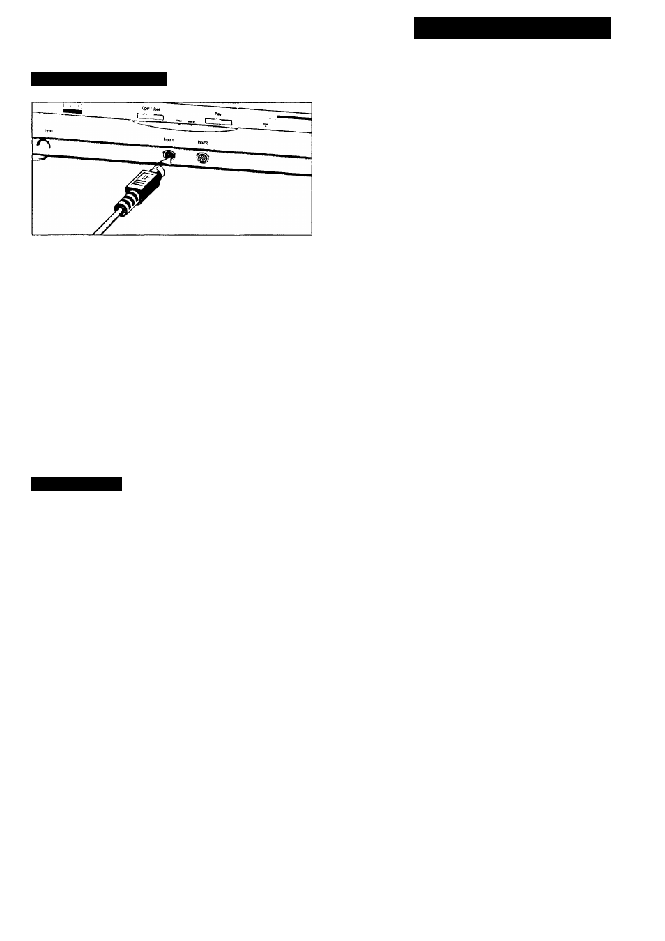
• Press the ON/OFF button (9) to switch the player off.
• Plug the connector of the CD-i controller into the input port
(12)
on the front of the player. Insert the connector with the
arrow at tlie top.
• Switch the player on.
• Move tlie cursor in the direction you want.
• Click on one of the action buttons.
- The function selected by this "point-and-click" technique is
highlighted to confirm the selection.
NOTE
-
To "point-and-click" on any screen shown in this manual,
either one of the action buttons of the pointing device can be
used.
- The shape of the cursor can be different depending on the
program you are playing, but it is always controlled in the
same way.
- Pointing devices are sensitive precision instruments. Handle
with care, keeping in mind the following precautions:
• Avoid dropping or knocking.
• Do not use in locations subject to extreme temperatures,
humidity, dust or vibration.
• Never hold the pointing device by the cable.
• Never pull the cable to disconnect the pointing device from
the player.
• When only one pointing device is used preferably, connect
it to input 1 to avoid problems with the remote control.
CAUTION
NEVER MAKE OR CHANGE CONNECTIONS WITH THE
POWER SWITCHED ON.
INTERFACES
RS 232C Ports
Extension Slot
I/O ports #1 and #2 (D-sub 9) on the rear panel can be used for
general RS 232C based devices according to the application.
Further information on this subject can be found in the CD-i
Technical Documentation.
Depending on the application, RS 232C based devices may also be
connected to CD-i I/O port #4 on the rear panel. For more
information, please refer to the Technical Documentation of this
CD-i player.
An extension slot provides opportunities for upgrading of system
functionality and establishment of communication facilities.
As functional requirements differ from one application to another,
it is of no use to offer a ‘‘standard” optional extension. Instead, a
tailor-made extension, on the basis of a flexible and optimal
specification, will be scheduled for each project.
13