Connection diagrams, 49 connection diagrams – Canon Digital Video Camcorder ZR900 User Manual
Page 51
49
Connection Diagrams
Turn off all the devices when making the connections and refer also to the instruction
manual of the connected device.
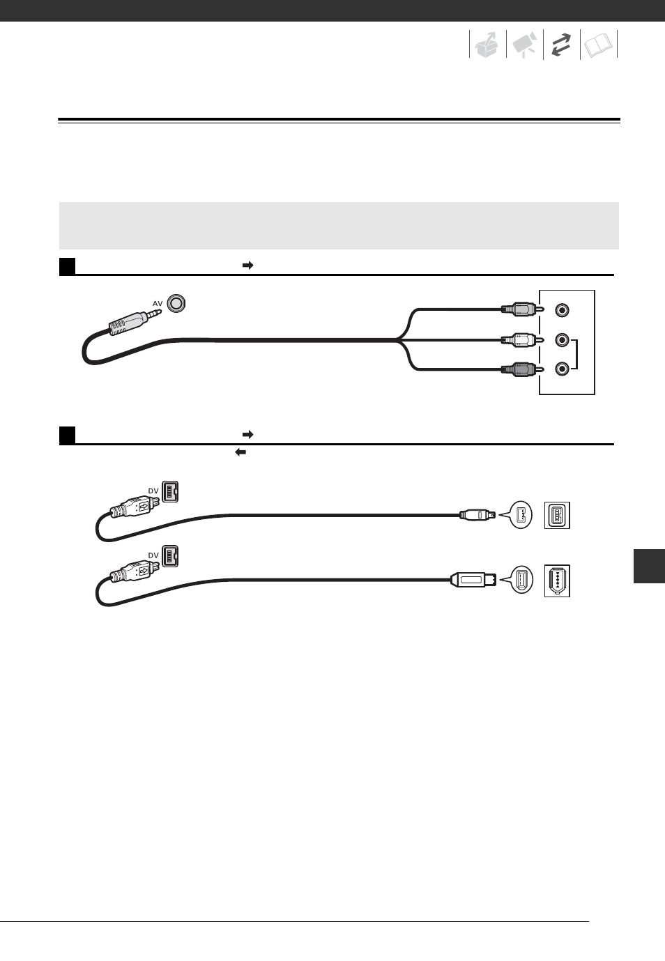
Terminal on the
Camcorder
Connecting Cable
Terminal on the
Connected Device
1
Output connection (signal flow
) to a TV or VCR with AV Terminals.
VIDEO
AUDIO
R
L
STV-250N Stereo Video Cable
(supplied)
Yellow
White
Red
2
Output connection (signal flow
) to a high-definition TV with a DV (IEEE1394) terminal.
Input connection (signal flow
) from a TV or other digital video source with a DV (IEEE1394) output.
DV cable
(commercially available)
4-pin
6-pin*
* Be careful to correctly insert the 6-pin plug into the DV terminal. Inserting it in the wrong direction
can result in damage to the camcorder.
This manual is related to the following products: