Testing the detector, Figure 8 - using the tester, Figure 7 - wiring diagrams – Interlogix ShatterPro 3 User Manual
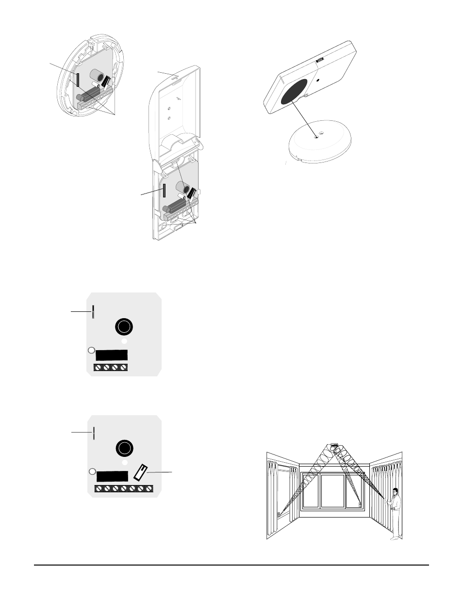
Page 3: Shatterpro 3 glassbreak detector, J3 spring clip, J3 spring clip tamper switch
3
ShatterPro 3 Glassbreak Detector
Testing the Detector
To verify detector range and operation, you need the Sentrol
5709C hand-held tester.
Use the following steps to test the detector:
1. Set the tester to the appropriate glass-type setting.
Use the tempered setting if you are unsure about the
glass type.
2. Put the detector in test mode as follows:
- Hold the tester close to the detector. See Figure 8.
- Activate the tester.
The LED on the detector lights for 4 seconds and then
starts flashing to indicate the detector is in test mode. The
relay opens for 4 seconds, then returns to standby.
3. Hold the tester near the surface of the glass to be pro-
tected and aim the speaker at the detector. Be sure the
tester is at the point on the glass farthestfrom the detector.
If closed drapes or curtains are present, hold the tester
behind them. See Figure 9.
4. Press the test button on the tester. The LED on the
detector should stay on for 4 seconds to indicate the
glass is within detection range of the detector. If the
LED does not stay on for 4 seconds, move the detector
and retest.
• S
in
g
le
• C
o
n
ti
n
u
o
u
s
P
la
te
•
T
e
m
p
e
re
d
•
L
a
m
in
a
te
d
•
Batter
y
LED
B
a
tt
e
ry
is
O
K
i
f L
E
D
s
ta
y
s
o
n
d
u
rin
g
t
e
s
t
5
7
0
9
C
S
h
a
tt
e
r S
e
rie
s
T
e
s
te
r
U
s
e
fo
r
te
s
tin
g
:
S
h
a
tt
e
rP
ro
S
h
a
tt
e
rb
o
x
S
h
a
tte
rb
o
x
I
I
S
h
a
tt
e
rS
w
itc
h
S
E
N
T
R
O
L
Figure 8 - Using the Tester
When the detector is in test mode,
the LED lights steady for 4 seconds,
then flashes for 60 seconds. Time
resets after each valid test.
1” (2.54 cm)
Hold the tester so that the speaker is
within 1” of the detector microphone.
Figure 6 - Detector Knockout Locations
Figure 9 - Testing the Range
J3 Spring clip
Knockouts
J3 Spring clip
Slot
Knockouts
GND +12V N.C. COM N.O. TAMP TAMP
GND +12V N.C. COM
J3 Spring clip
Figure 7 - Wiring Diagrams
J3 Spring clip
Tamper Switch
Models:
5812NT
R5812NT
Models:
5815NT
R5815NT