Ge security, Connection and programming, Specifications – Interlogix AP669 User Manual
Page 2
Access to the Mirror Inside the
Sensor Module
This access is only required when masking
individual curtains.
Undo the screw (5) and open the sensor
module (6) (see Figure 1).
The two mirrors are accessible now.
Selecting the Coverage Patterns
Mask the appropriate mirror curtains with
the adhesive labels provided and
reassemble the sensor module.
For example, see Figure 4 for mirror
curtain coverage pattern corresponding to
curtain 4 and 8 masked.
Masking Coverage Patterns
Field of View
Input power ............................................................... 12 or 24V (7–28V)
Peak to peak ripple ...................................................... 2V max. (at 12V)
Current consumption
Normal operation .................................................... 11 mA (at 12V)
Alarm ............................................................. 13 mA max. (at 12V)
Specified mounting height ..................................... 8 – 16 ft (2.4 - 4.8m)
Target speed range ............................................ min. 0.9 – max. 12.0 ft/s
Alarm output ....................................................... 50 mA at 28 V Form C
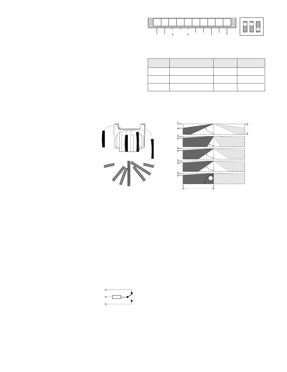
Connection and Programming
Switch 1: Programming the LED
ON
LED enabled
OFF
LED disabled
Switch 2: Programming the processing
ON
Enables Bi-curtain processing designed for harsh environment.
OFF
Provides the standard 4D processing.
Switch 3: Programming the detection pattern
ON
Provides a 180° field of view for special applications.
OFF
Gives the normal 360° field of view.
Note:
An arrow in the mounting plate (4) (see Figure 1 and Figure
2) and inside the sensor module shows the always active coverage
pattern. The coverage pattern opposite to the arrow can be disabled
by setting switch 3 in the “ON” position.
Alarm time ............................................................................ min 2.5 sec.
Tamper output ................................................................. 100 mA at 28 V
Temperature limit ............................... 0°F to +131°F (–18°C to +55°C)
Relative humidity .................................................................... max. 93%
Size ................................. 5.43 in. dia. x 2.68 in. (138mm dia. x 68 mm)
Weight ................................................................................... 4.25 ounces
Number of curtains .............................................................................. 18
Max. detection range ................. 60 ft (18m) diameter, 30 ft (9m) radius
Listings ..................................................................................... C-UL US
Figure 3
Figure 4
Specifications
1 2 3 4 5 6 7 8 9
1
ON
10
ñ
+
ALARM
NC C NO
TAMPER
SPARE
2
3
5
4
3
2
1
6
7
8
9
1 2 3
4
5
6 7
8
9
30'
1.8 ft
shaded area is shunted
when switch 3 is ON
90°
1.8 ft
1.8 ft
48°
48°
1.8 ft
20°
5.4 ft
60°
Mounting Height
8—16 ft
1 & 9
2 & 8
3 & 7
4 & 6
5
33
Ω
Switch
Description
On
Off
1
LED enable
LED on
LED off
2
Processing
Bi-curtain
Standard-4D
3
Detection pattern
180°
360°
Mounting Height Application Note
When increased mounting heights are used outside the specified mounting height range of 8 - 16 ft (2.4 - 4.8m), sensitivity will be reduced.
14012 Rev C 03/04
Tech Support
800-648-7424
FaxBack: 800-483-2495
www.ge-security.com
GE Security
12345 SW Leveton Drive
Tualatin, OR 97062
503-692-4052
USA & Canada: 800-547-2556
GE Security
g