Wiring – Interlogix 6255 Series User Manual
Page 2
6255 SureShot PIR
2
3. Mount the back cover to a ceiling, wall, or corner. For wall
mounting, make sure the "up" arrow is pointing up. Use the
appropriate mounting knockouts. See Figure 3.
4. Snap the circuit board assembly onto the back cover by
aligning the lower edge of the board with the circuit board
guides and pressing it into place. See Figure 1.
5. Connect the wires (see Wiring and Figure 7).
6. Choose which masking plate you need, if any. Insert it
behind the lens on the front cover by pressing it over the
four mounting pins. Once the front cover is installed, the
masking plate will be held tight against the lens.
Note
The masking plates have two notches to prevent
incorrect installation. One notch matches a rib in
the front cover. The other notch matches a dimple
in the lens. See Figure 4.
Note
To correctly mount the Pet Alley Mask, the lens
must be removed from the front cover and rotated
180 degrees. See Figure 5.
7. Replace the front cover.
Note
When mounting on the ceiling, align the unit to
maximize the oblong detection pattern for the
room. See Figure 6.
Note
The unit should be connected to a UL listed power supply
capable of providing four hours of standby power.
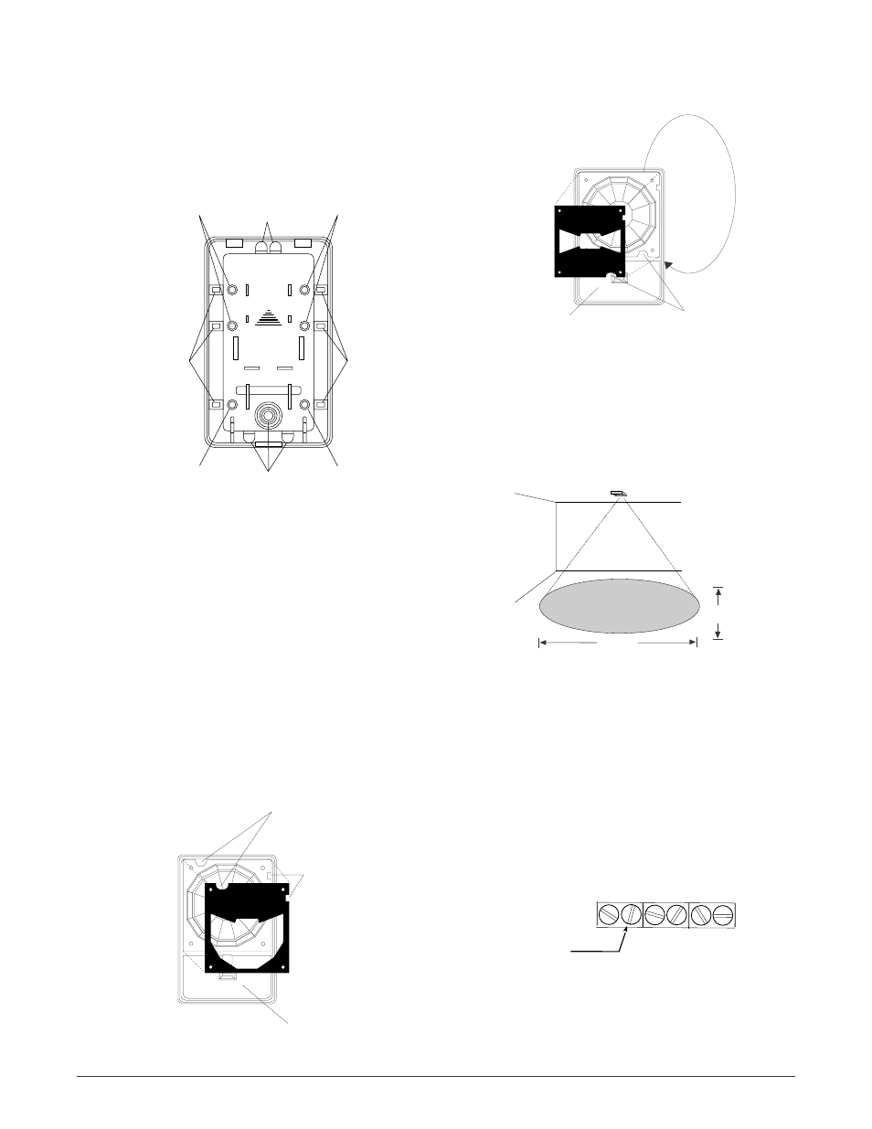
Figure 4. Masking plates
WIDE
ANGLE
Align notch
with dimple
Align notch
with rib
Inside of
front cover
Figure 3. Back cover
UP
MADE IN U.S.A.
1-800-547-2556
Wall or ceiling
mounting
knockouts
Wall or ceiling
mounting
knockouts
Wall or ceiling
mounting
knockouts
Wall or ceiling
mounting
knockouts
Wiring knockouts
Wiring knockouts
Corner mounting
knockouts
Corner mounting
knockouts
Figure 6. Detection pattern
Capture zone
at 8.0' (2.4m) mounting height
15.0'
4.59m
20.0'
6.12m
Figure 7. Wiring
8. After walk testing, the LED cover can be used to cover
the LED. See Figure 1.
Strip back the outer jacket on the wiring cable. This will
allow wires to flex in the case. Use the cable strain relief
built into the back cover to prevent stressing wires at
their connection. See Figure 1.
Wiring
+
–
Power-In
7 to 16 VDC
NC COM Tamp Tamp
PET
ALLEY
ROTATE LENS
180
o
Rotate lens 180
°
Align notch
with dimple
Inside of
front cover
Figure 5. Pet alley mask