Sentrol, Specifications, Accessories – Interlogix 5820A Series User Manual
Page 4
U.S. & Canada: 800.547.2556
Technical Service: 800.648.7424
FaxBack: 800.483.2495
CORPORATE HEADQUARTERS
SENTROL
Electrical
Voltage ...................................................................... 9 to 16 VDC
Current ............................................... 12 mA typical, 25 mA max.
Relay output ............Normally closed, open 4 seconds upon alarm
On resistance ................................................ 10 Ohm 5 +10
Off resistance ....................................................... > 1 MOhms
Maximum loop rating (relay or tamper loop) .........................
...................................................................... 16 VDC, 50 mA
Wiring terminals .........................................................22-18 AWG
Environmental
Lightning suppression .......................... 400 watts for 1 msec pulse
RF Immunity .............................. 20V/m min from 1MHz to 1GHz
Microphone............................................ Omni-directional electret
Operating Temperature ............. 0° F to 120° F (-18° C to +50° C)
Humidity ............................................10% to 90% noncondensing
SPECIFICATIONS
NOTE: This equipment has been tested and found to comply with the limits for
a Class B digital device, pursuant to Part 15 of the FCC Rules. These limits are
designed to provide reasonable protection against harmful interference in a
residential installation. This equipment generates, uses and can radiate radio
frequency energy and, if not installed and used in accordance with the instruc-
tions, may cause harmful interference to radio communications. There is no
guarantee that interference will not occur in a particular installation. If this
equipment does cause harmful interference to radio or television reception, which
can be determined by turning the equipment on and off, the user is encouraged to
try to correct the interference by one or more of the following measures:
Re-orient or relocate the receiving antenna.
Increase the separation between the equipment and receiver.
Connect the equipment into an outlet on a circuit different from that to which
the receiver is connected.
Consult the dealer or an experienced radio/TV technician for help.
Under FCC Rules, Part 15 for Class B digital devices, operation is subject to the
following two conditions:
1) This device may not cause harmful interference.
2) This device must accept any interference received, including interference
that may cause undesired operation.
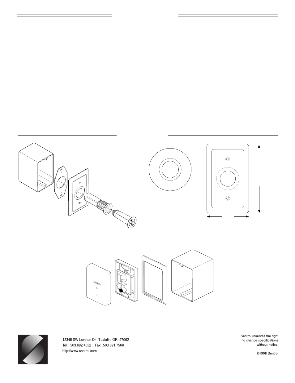
ACCESSORIES
2.75"
(6.99 cm)
4.5"
(11.43 cm)
5829A Single Gang Box Plate
for 5820A.
5825A Single Gang Box
ShatterPro
™
II
5812EZ Pre-Wire Installation with 5811EZ and Single Gang Box
G-3513-798
15651 Rev. A
(Back box
not included)
(Back box
not included)
2.53" diameter (6.43 cm)
1" diameter hole (2.54 cm)