Interlogix 600-1053-4 User Manual
Page 3
600-1053-4 Concord 4 CDMA Module Installation Sheet
3
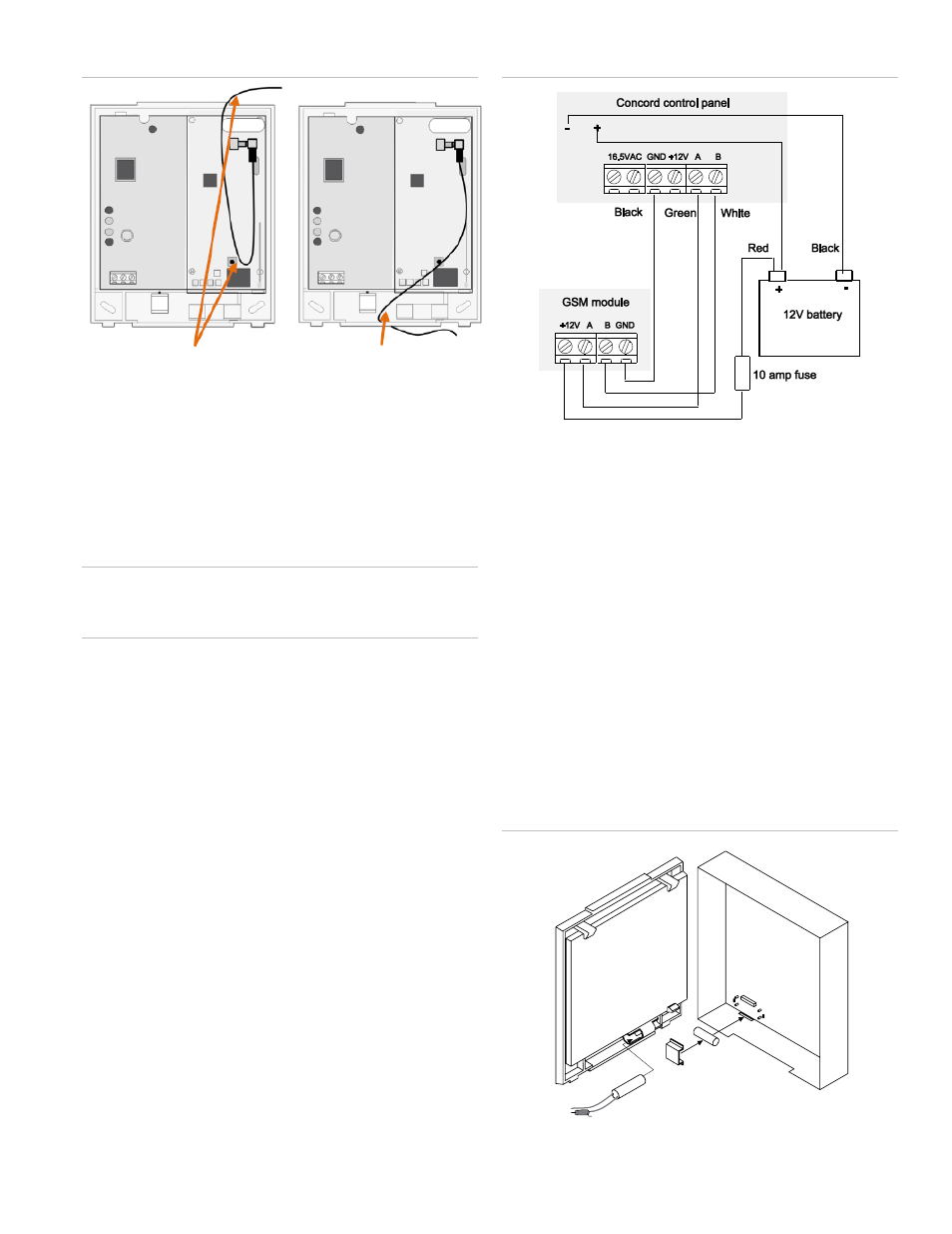
Figure 2: Antenna Routing
5. Set the backplate aside and drill holes at the mounting and
wire access area locations.
6. Use wall anchors where studs are not present and secure
the backplate to the wall with the enclosed screws.
Wiring
Caution:
To prevent damaging the panel or module, you must
remove panel AC power and disconnect the backup battery
before making or changing wiring connections.
To wire the module:
1. Remove AC panel power and disconnect the backup
battery.
2. Wire the module to the panel bus and to the battery
terminals for power. (The module can also be powered off
the SuperBus 2000 two-amp power supply (600-1019), but
should not be powered directly off the panel.)
3. You can connect an input device to the module Z1 and
ZCOM terminals if required.
Figure 3: Wiring connections
Case tamper switch (optional)
If the module is easily accessible, you can add case tamper
detection to activate an alarm or trouble (depending on panel
programming) when the cover is removed.
To install the tamper switch:
1. Slide the reed switch into the plastic holder on the module
backplate.
2. Connect a UL-Listed reed switch (with 2 Kohm EOL
resistor) to the module zone input or to any unused
hardwired input on the panel.
3. Insert the magnet into the nibs on the top cover and press
the magnet clip down over the magnet until it clicks into
place into the cover.
Figure 4: Case tamper switch
Backplate
Cover
Magnet
Magnet clip
Reed switch
2.0 kohm EOL resistor
Loop antenna and feed -OR-
back through top of module
Feed antenna through wire
access area and into wall