IC Realtime 4 Channel PoE Mobile Network Video Recorder User Manual
Page 72
63
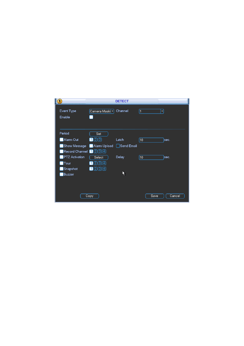
4.7.7.3 Camera Masking
When someone viciously masks the lens, or the output video is in one-color due to the
environments light change, the system can alert you to guarantee video continuity. Camera
masking interface is shown as in Figure 4-64. You can enable alarm output channel and then
enable show message function. You can refer to chapter 4.7.7.1Motion detect for detailed
information.
Tips:
You can enable preset/tour/pattern activation operation when video loss occurs.
Note:
In Detect interface, copy/paste function is only valid for the same type, which means you can
not copy a channel setup in video loss mode to camera masking mode.
Figure 4-64
4.7.8
PTZ
Note: All the operations here are based on PELCOD protocol. For other protocols, there might
be a little difference.
Cable Connection
Please follow the procedures below to go on cable connection
Connect the dome RS485 port to NVR 485 port.
Connect dome video output cable to NVR video input port.
Connect power adapter to the dome.
PTZ Setup
Note: The camera video should be in the current screen. Before setup, please check the
following connections are right:
PTZ and decoder connection is right. Decoder address setup is right.
Decoder A (B) line connects with NVR A (B) line.
Boot up the NVR, input user name and password.